Analysis of MRAC Correction Scheme for CNC Machine Tool Cutting Process
Cutting on a system that includes machine tools, cutting tools, and workpieces is a complex and dynamic process influenced by various factors such as uneven material stock, differences in material hardness, tool wear, built-up edge formation, cutting forces, deformation, vibration, and thermal effects. These unpredictable variables can prevent the cutting process from operating at its optimal level, which negatively affects production efficiency, machining quality, and economic benefits. In severe cases, it may even disrupt the normal progression of the cutting operation. To address this issue, adaptive control methods for machine tools were introduced in the 1960s. These techniques allow for real-time adjustments to cutting parameters based on changing conditions during the machining process.
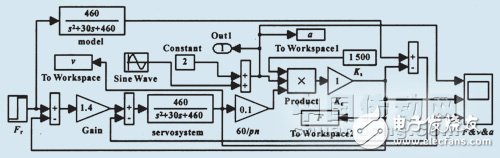
Based on the concept of Model Reference Adaptive Control (MRAC), an MRAC model for CNC machining was developed, followed by dynamic simulation of the system. The performance of feedback closed-loop control, open-loop control, and MRAC was compared through simulation. The results showed that MRAC provided the best cutting performance index, demonstrating its effectiveness in maintaining stable and efficient machining operations.
**1. Working Principle of CNC Machine Tool MRAC**
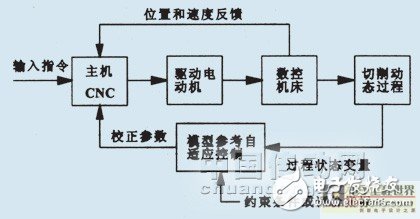
The MRAC system in a CNC machine tool is designed to adjust the cutting process based on the interaction between the machine, tool, and workpiece. The control system structure is illustrated in Figure 1. In addition to the standard position and speed control loops found in conventional CNC systems, MRAC introduces an additional feedback loop. When disturbances occur due to various random factors, the state parameters of the cutting process change rapidly. These parameters are continuously monitored by sensors and converted into signals that are processed within the MRAC control unit. By comparing the actual performance with the desired reference index, the system calculates the deviation and generates correction signals to adjust the input parameters of the CNC system. This ensures that the cutting process remains within the desired performance range, achieving optimal operation.
**2. Establishment of MRAC Model for Machine Tool Cutting**
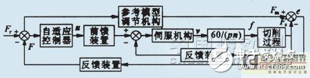
The MRAC model for the cutting process is shown in Figure 2. It consists of several key components: a servo mechanism, the cutting process itself, a reference model adjustment mechanism, a feedforward device, and a feedback device.
The servo link can be represented as a second-order system:
$$
G(s) = \frac{K_n}{s^2 + 2\xi\omega_n s + \omega_n^2}
$$
Where:
- $ s $ is the Laplace operator.
- $ u $ is the servo input voltage (V).
- $ K_n $ is the servo gain (mm/(V·s)).
- $ \omega_n $ is the natural frequency (rad/s) of the servo system.
- $ f $ is the feed rate (mm/s), which can be expressed as:
$$
f = \frac{n \cdot p}{60}
$$
Where:
- $ n $ is the spindle speed (r/min).
- $ p $ is the number of teeth on the tool, typically $ p = 1 $ for turning operations.
The reference model adjustment mechanism is assumed to represent ideal performance, so it follows the same structure as the servo mechanism.
During the machining process, the static cutting force $ F_s $ can be expressed as:
$$
F_s = K_s \cdot a^m
$$
Where:
- $ K_s $ is the specific cutting force (N/mm²).
- $ m $ is an exponent (typically $ m < 1 $).
- $ a $ is the depth of cut (mm).
For different machining conditions, the dynamic behavior of $ F_s $ can also be modeled using equation (3). Assuming $ m = 1 $, the dynamic process can be approximated as a first-order system:
$$
F_s(t) = K_s \cdot a \cdot (1 - e^{-t/\tau})
$$
Where:
- $ \tau $ is the time constant.
The feedforward and feedback devices in the model are proportional links with a scaling factor of $ K $.
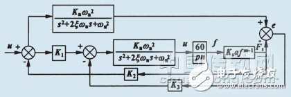
By combining all these elements, the mathematical control model for the MRAC system in the cutting process is established, as shown in Figure 3.
Optical Prism,Dispersion Prism,Si Right Angle Prism,Chandelier Prisms
Danyang Horse Optical Co., Ltd , https://www.dyhorseoptical.com