About polar capacitors and non-polar capacitors
I came across a statement online saying, "To connect the anodes or cathodes of two electrolytic capacitors in series to create a non-polar electrolytic capacitor." I’m confused by this. Electrolytic capacitors are inherently polarized, right? So if you connect their anodes or cathodes in series, wouldn't that still result in a polarized component? If you apply a voltage after connecting them in series, there would be a risk of electrolysis because the polarity might reverse on one of the capacitors. How does that prevent breakdown? I’d really appreciate it if someone could explain this clearly. Thank you!
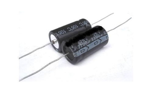
Non-polar electrolytic capacitors are readily available, and our company uses them regularly from reputable manufacturers.
Of course, they aren’t just two electrolytic capacitors packed into one case. Instead, they have two layers of etched aluminum oxide film inside.
If you remove the electrolyte, you’ll notice the two layers of aluminum foil are different: one is thin and smooth, while the other is thick and rough. The latter is actually corroded and oxidized, with the insulating layer being the oxide film on its surface.
Because these two layers have different structures, they each have a polarity. When both are oxidized, the result is a non-polar capacitor—though not through electrolysis, but through design.
As for the claim that "connecting two electrolytic capacitors' anodes or cathodes in series can form a non-polar capacitor"—this isn’t entirely wrong, but it’s risky.
When a capacitor is connected in reverse, the leakage current increases significantly due to the low reverse insulation resistance of the oxide layer. This causes excessive heat, leading to electrolyte expansion, evaporation, or even rupture. However, when two electrolytic capacitors are connected in series, it's like having two diodes in reverse. In either direction, the reverse voltage drop is small, so most of the voltage falls on the forward-biased one. This prevents overheating, and the overall insulation resistance becomes higher than that of a single capacitor.
But this method requires using two identical capacitors. If they’re too different, it won’t work well and could lead to failure.
For safety, this approach is only suitable for low-voltage and low-energy applications. It should never be used under high voltage.
The key assumption here is that the forward resistance of an electrolytic capacitor is much greater than its reverse resistance. Otherwise, this method won’t work.
This needs to be considered during both transient and steady-state conditions in the circuit.
Assume the two capacitors are initially connected with their positive terminals toward the same direction before applying AC voltage. Imagine they're connected in parallel with a diode, where the diode’s cathode is positive (it might help to draw this out for better understanding).
During the first half-cycle, the left capacitor charges through the diode, and during the second half-cycle, the right capacitor discharges and charges the left one. This continues until the voltage across both capacitors reaches the peak of the AC signal.
After that, the diodes stop conducting, and the capacitors are effectively in series. Their combined capacitance becomes half of one individual capacitor.
Now, if we remove the diodes and consider the fact that the forward resistance of the electrolytic capacitor is much higher than the reverse resistance, it’s similar to having a diode in parallel with the capacitor and a resistor in parallel as well. The forward resistance allows some discharge, but otherwise, the behavior is similar to the diode setup.
The two negative terminals of the capacitors are connected to the negative pole, and the configuration ends up with two positive electrodes and one dielectric layer. This forms a non-polar electrolytic capacitor.
I still find the explanation above a bit unclear. It says, "charge until the voltage across the two capacitors equals the AC peak," but in that case, the voltages would be opposite. If you connect them in series, the total capacitance would effectively be zero. If you consider DC only, the “parallel diode†method seems to suggest only one capacitor gets charged, which contradicts the idea of a series connection.
Let me clarify: For pure DC, capacitors act as open circuits, so they don’t charge. To observe any effect, there must be an AC component superimposed on the DC.
You should use a signal with an AC component and analyze the circuit once it reaches a steady state based on the parallel-diode model. At that point, both diodes are off, and no current flows. One capacitor will be charged to the peak of the signal, which includes the DC offset. The total capacitance remains half of one capacitor.
Circular Saw Blade Polishing Machine
Circular Saw Blade Polishing Machine,Automatic Saw Blade Polishing Machine,Efficient Saw Blade Polishing Equipment,Polishing Machine For Saw Blade
Suzhou Mountain Industrial Control Equipment Co., Ltd , https://www.szmountain.com