Teach you to understand the physical meaning of the common parameters of the speaker
The parameters of the speaker refer to the specific performance parameter values ​​of the speaker tested by the dedicated speaker test system. The commonly used parameters mainly include: Z, F0, η0, SPL, Qts, Qms, Qes, Vas, Mms, Cms, Sd, BL, Xmax, Gap gauss. The following are the physical meanings of these parameters: 

First, the physical meaning of the parameters
1, Z: refers to the resistance value of the speaker, including: rated impedance and DC impedance. (Unit: ohm / ohm), usually refers to the rated impedance;
The rated impedance Z of the speaker is the minimum impedance modulus after the first maximum of the impedance curve, which is the impedance value corresponding to point B in the figure below. It is the reference for calculating the electric power of the speaker.
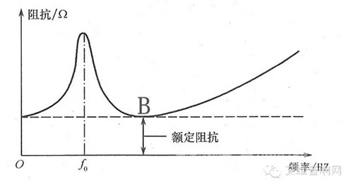
Rated impedance
DC Impedance DCR: refers to the impedance value measured by the DC signal when the voice coil coil is stationary. We usually say that 4 Euro or 8 Euro is the rated impedance.
2. Fo (the lowest resonance frequency) refers to the frequency corresponding to the first maximum value of the speaker impedance curve. Unit: Hertz (Hz).
The impedance curve of the loudspeaker is a plot of the impedance modulus of the loudspeaker as a function of frequency measured by constant current or constant voltage under normal operating conditions.
3, η0 (the efficiency of the speaker) refers to the ratio of the speaker output sound power to the input power.
4. SPL (sound pressure level) refers to the sound pressure generated by the horn on the reference axis at a distance of 1 m from the horn when the voltage of the rated power is 1 W. The unit is decibel (dB).
5, Qts: the total quality factor of the speaker.
6, Qms: the mechanical quality of the speaker due to the value
7, Qes: The electrical quality factor of the speaker.
8. Vas (effective volume of the horn): refers to the volume when the air in the rigid container is equal to the sound of the speaker unit. Unit: liter (L);
9. Mms (Vibration Quality): refers to the sum of the masses of the components involved in the vibration during the movement, including the drum paper part, the voice coil, the elastic wave and the air quality involved in the vibration. Unit: gram.
10, Cms (force): refers to the flexibility of the support components of the speaker vibration system. The greater the value, the softer the entire vibration system of the speaker. Unit: mm / Newton (mm / N).
Second, the nonlinear distortion of the speaker
The loudspeaker exhibits a number of additional signal components when reproducing the sound, resulting in nonlinear distortion. It mainly has the following types.
1, harmonic distortion
The magnetic field is not uniform in the magnetic gap, the edge loop of the vibration system and the centering of the centering piece can cause harmonic distortion in the case of large amplitude. This distortion always occurs in the low frequency band. The lower the frequency, the larger the cone amplitude and the more obvious the harmonic distortion.
2, modulation distortion
The voice coil of the speaker simultaneously inputs low frequency and high frequency signals, such as low frequency 100~200HZ, high frequency 6~7KHZ, the paper cone vibrates at the same time, and the high frequency sound vibration modulates the low frequency phenomenon, which will inevitably cause modulation distortion and make the sound color deteriorate. Stiff.
3, transient distortion
The voice coil of the speaker is driven by a current, which causes the cone to vibrate and pronounce, and this will inevitably produce a certain inertia. In order to achieve stability, the inertia system takes a certain amount of time. If this settling time is too long, various extremely fast signals will follow, and the vibration of the paper cone cannot keep up with the signal changes, resulting in playback distortion, especially in the shape of a pulse. The sound is most obvious.
4, subharmonic distortion
Partial harmonic distortion is an inherent distortion of the cone speaker. During the positive half of the input signal, the cone bends upwards. During the negative half of the signal, the cone is bent slightly downward due to inertia, and will only move downward when the positive half of the next input signal arrives. Therefore, the movement of the cone is only half of the signal frequency, causing subharmonic distortion. This distortion is more pronounced for straight-shaped cones, while the index-shaped cones produce almost no subharmonic distortion.
Third, the speaker's maximum linear displacement volume
The maximum linear displacement Xmax is the limit of the one-way displacement of the cone when the speaker unit is working, and the unit is MM. When the one-way amplitude of the speaker cone exceeds this limit, the number of voice coils of the cutting magnetic field is reduced, resulting in a decrease in the driving force of the voice coil, and the output sound pressure of the speaker enters a non-linear state, and the distortion is significantly increased.
The maximum linear displacement Xmax of the loudspeaker unit and the effective vibrational area Sd of the loudspeaker unit is what we usually call the maximum linear displacement volume Vd which determines the maximum air volume that the loudspeaker can push when it radiates sound.
The maximum linear displacement volume of the speaker largely determines the maximum output sound pressure level of the speaker unit at the lowest frequency end. The larger the maximum linear displacement volume value of the speaker, the sound pressure that the speaker unit can radiate at a lower frequency. The higher the speaker size, the larger the effective vibration area and the larger the linear displacement. Therefore, the speaker has a higher low-frequency output sound pressure level.
The equivalent volume of the speaker unit means that after a certain speaker unit is placed in a box with a certain internal volume, if the sound of the air in the box is exactly equal to the sound of the speaker unit used, then the internal volume of the box is The equivalent volume of the speaker unit, the equivalent volume of the speaker is referred to as Veq.
The equivalent volume Veq of the speaker unit together with the quality factor Q resonant frequency F of the loudspeaker determines the low frequency characteristics of the loudspeaker. Therefore, it is also one of the important parameters for designing a speaker.
Fourth, the speaker power characteristics
The value of the power parameter identified on the speaker is one of the important indicators of the product. Due to the inconsistency in the definition of speaker power quality indicators at home and abroad, the confusion of the same product specifications has been caused. In order to eliminate this confusion, China issued a new standard in 1985, and passed the new national standard GB9396-9400 in 1988. In 1996, it was revised to the new national standard GB9396-9397-1996.
In the new ministry and the new national standard, combined with the "Electro-acoustic device - speaker" and "the minimum requirements for speakers in high-fidelity equipment" issued by the International Electrotechnical Commission, the speaker quality index ---- power is defined as characteristic power, maximum Noise power (rated noise power), maximum sinusoidal power, long-term power, (rated long-term power), and short-term power.
1, the nominal power
The nominal power is measured by the continuous, sine wave rms power, and is determined by the speaker distortion index. For example, if a speaker mark distortion is less than 3%, the distortion is 3% at 5W, then this speaker is The nominal power is 5W.
2, characteristic power
Characteristic power means that in the frequency range of 100~8000HZ, the meter inputs a pink noise signal to the speaker system, and generates a 94dB characteristic sound pressure level from the sound source 1M, the value of which depends on the sensitivity of the speaker.
3. Maximum noise power (rated noise power)
The speaker system is specified to be tested with a special test noise signal to the speaker 100H within a certain rated frequency range (the spectrum of the noise signal is closer to the actual program signal), and the result is no overheating and mechanical damage, achieving long-term safe operation. The power thus tested is called the rated noise power. This power is independent of distortion, so it tends to be 2 to 4 times larger than the nominal power. Foreign speakers generally identify this power, and domestic speakers are gradually using this power meaning setting.
4, the maximum sinusoidal power
The speaker system feeds a continuous sinusoidal power test over a range of frequencies. As a result, the speaker voice coil vibration should not produce a sound, nor excessive heat or mechanical damage. Since this power is not limited by the distortion value, the power is higher than the nominal power.
5, long-term power (rated long-term maximum power)
The speaker system feeds a specially specified noise signal power test over a range of frequencies. The speaker will not be subjected to permanent mechanical damage within 1 min of this power, and it will be tested once every 2 minutes and repeated 10 times. This power is much larger than the rated noise power.
6, period power
In a certain frequency range, the power of the noise signal specified by the speaker system is tested, and the power of the speaker does not cause permanent mechanical damage within 1S, and the power is short-term power. It has the highest value in all named powers and can be 8 to 10 times larger than the nominal power.
7, music power
Power is primarily dependent on the speaker's ability to withstand short-term sinusoidal signal frequencies below 250 Hz. The speaker is subjected to this power, and through actual tests, there is no significant distortion, no overheating and mechanical damage. The music power standard is derived from the German DIN45500 standard, which is the actual value of the integrated power.
At present, noise generators are mostly used when testing loudspeakers to withstand power. Noise is an irregular, intermittent signal. Generally, the noise signal used for testing has white noise and pink noise. The words "white" and "pink" are determined by the spectrum of these two kinds of noise.
White noise is a kind of random noise. The noise signal contains various frequencies from 20HZ to 20KHZ, and the energy of these signals is evenly distributed. Pink noise is also a kind of random noise, but its energy distribution is inversely proportional to the frequency, so The low-frequency components in pink noise are more. When testing, the power amplifier feeds a certain signal power to the speaker under test. The ratio of the square of the effective value of the voltage input across the speaker to the measured speaker impedance is the power of the speaker. .
Five, speaker quality factor
The quality factor of the speaker unit is one of the important parameters that must be understood before designing and making the speaker. On the impedance characteristic curve of the speaker unit, it indicates the sharpness of the impedance peak of the impedance curve at the resonance frequency. It reflects the damping state of the speaker vibration system to a certain extent, referred to as Q value.
The quality factor of the speaker unit reflects the speed of the speaker cone returning to a standstill after the electrical signal input to the speaker unit disappears, or the damping effect of the speaker unit electromagnetic system on the vibration system, that is, reflecting the transient response of the speaker unit. Good or bad. The higher the quality factor of the speaker unit, the slower the energy consumed by the speaker vibration system and the less easily the resonance is controlled.
The low frequency characteristics of the loudspeaker are usually determined by the quality factor Q of the loudspeaker unit and the resonant frequency F to determine the effect of the Q value on the output sound pressure at F:
When the Q value is too low, the output sound pressure of the speaker will drop rapidly when it is not at F, and the speaker is in an overdamped state, causing the low frequency attenuation to be too large.
When the Q value is too high, the output sound pressure of the speaker will have a peak at F, the speaker is in an underdamped state, and the low frequency is excessively strengthened. The larger the Q value, the steeper the peak value.
Therefore, the quality factor Q of the speaker should not be too high or too low. We generally take its critical damping value, that is, Q equals 0.2~0.6 as the optimal value range.
Speaker impedance characteristics
The impedance of the marker on the speaker in Ω. The impedance of a speaker unit is usually expressed by its impedance characteristics and rated impedance, but the two are two completely different concepts.
1. Impedance characteristics
The speaker voice coil is a coil made of an enameled wire on a cylindrical skeleton. It has a certain inductance in addition to a certain DC resistance. When the audio signal is input, the speaker voice coil vibrates up and down in the magnetic air gap. Due to the effect of the voice coil inductance, an induced voltage that is opposite to the audio signal is induced in the voice coil. This induced voltage opposite to the audio input signal weakens the current in the voice coil, thereby making the voice coil impedance Increase.
As the frequency of the audio signal rises, the effect becomes larger and larger, which increases the impedance of the speaker voice coil as the frequency of the audio signal increases. The law that the impedance of the speaker unit varies with the signal frequency is called the impedance characteristic of the speaker unit.
2, rated impedance
The rated impedance of the speaker unit is the resistance of a pure resistor, which is the first impedance minimum of the speaker unit under test after the resonant frequency. At this time, the counter electromotive force generated by the voice coil self-inductance and the counter electromotive force generated by the voice coil vibration cancel each other out due to the opposite direction, so that the impedance value of the speaker is most similar to the DC resistance of the voice coil.
China National Standard GB9399-88 "Main Technical Parameters of Speakers" stipulates that the rated series of rated impedance values ​​of speaker units are: 2, 4, 8, 16 and 32 Ω. At present, most domestic and international speakers have a rated impedance of 4 Ω or 8 Ω.
The rated impedance of the loudspeaker is given by the loudspeaker manufacturer and is indicated on the product label or on the lower magnetic guide of the loudspeaker. The rated impedance of the speaker can also be estimated based on the DC resistance of the speaker voice coil. Multiplying the DC coil resistance of the speaker voice coil measured by the multimeter by 1.1 to 1.3 times is the rated impedance speaker frequency characteristic of the speaker.
The frequency characteristic of the speaker refers to the law that the output sound pressure of the speaker on the reference axis changes with the frequency of the input signal when the signal voltage of the input speaker is constant. Frequency characteristics are also an important indicator of their quality. The requirement for the speaker frequency is to determine whether the frequency range of the reproduced audio signal can meet the requirements, so the actual frequency characteristic curve must be determined.
1, frequency response curve
The test must be carried out in an anechoic chamber. At present, the frequency response curve of most speakers is measured under the condition of 1M*1W, that is, the signal power input to the speaker unit under test is 1W; the measurement microphone is located along the reference axis of the speaker unit under test from the emission surface of the speaker 1M; the signal generator The output signal is amplified by the power amplifier and fed to the speaker under test. The sound signal radiated by the measured speaker is received by the measuring microphone and converted into an electrical signal, which is processed by the measuring amplifier and sent to the level recorder. When the frequency of the output signal of the signal generator changes, the corresponding change in the sound pressure output from the speaker is simultaneously recorded by the level recorder. This is the frequency response curve of the speaker unit under test.
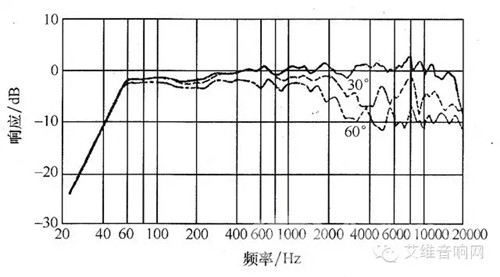
Frequency response curve
2. Effective frequency range
Select an octave wideband in the region with the highest sound pressure level on the frequency response curve of the tested speaker unit. (A octave refers to a frequency interval of two frequency ratios of two, for example, 500~1000HZ, 3000~6000HZ is a The octave is calculated as the average sound pressure level of the bandwidth, and then the average sound pressure level is used as a reference, and a line parallel to the X-axis is made 10 dB below the average sound pressure level. The frequency range between the frequencies corresponding to the two points at which the horizontal line intersects the frequency response curve of the speaker is what we often call the effective frequency range of the speaker.
When the input signal frequency of the electric speaker is lower than its resonant frequency, the output sound pressure of the speaker drops at a rate of 12 dB per frequency. Therefore, the International Electrotechnical Commission IEC specifies the resonant frequency of the speaker unit as the low frequency lower limit frequency of the speaker. And the intersection of the high frequency end of the speaker unit frequency response curve is taken as the high frequency upper limit frequency of the speaker. The range of frequencies between them is called the effective frequency range of the speaker.
Sometimes speaker manufacturers also offer an indicator called the speaker's rated frequency range. The effective frequency range and rated frequency range of the speaker are two different concepts. The former refers to the speaker unit can effectively reproduce the signal frequency range that meets certain sound pressure level requirements, and the latter is the speaker manufacturer's product standard according to the speaker unit. The optimum operating frequency range specified for use.
3, unevenness
Ideally, the speaker frequency characteristic curve is as flat as possible, but the measured speaker frequency response curve is usually an irregular continuous curve with many peaks and valleys. The difference between the maximum sound pressure level and the minimum sound pressure level on the frequency response curve in the effective frequency range of the measured loudspeaker is called the unevenness of the speaker unit, and the peaks and valleys narrower than 1/9 octave can be ignored. Excluding.
The high energy from short wavelength UVC light is absorbed in the cellular RNA and DNA, damaging nucleic acids and preventing microorganisms from infecting and reproducing.
This absorption of UVC energy forms new bonds between nucleotides, creating double bonds or dimers." Dimerization of molecules, particularly thymine, is the most common type of damage incurred by UVC light in microorganisms.
Formation of thymine dimers in the DNA of bacteria and viruses prevents replication and ability to infect.
Disinfecting Light UV,Sterilization UV Lamp,Sterilization UV Disinfecting Light,Germicidal Tube Lamp with Base
Jilin Province Wanhe light Co.,Ltd , https://www.wanhelight.com