Texas Instruments Automotive Sensors (Vehicle Hydraulic Valves) Solutions
Hydraulic valve
This article refers to the address: http://
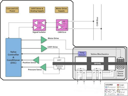
The hydraulic valve indicates the flowing liquid medium, usually the input port from which the oil passes to its output. The direction of the oil flow is determined by the spool, which is driven by the position of the linear force motor:
The core subsystems include:
Power conversion
• Isolation valve power, external busbars, and 24V supplies are provided between the galvanic couples. It also provides regulated supply voltages for individual function blocks.
Field bus interface and control
• Provide galvanic isolation between the system controller and the field bus signal. The system controller switches the valve command dsp to the field bus from the incoming data. It will also translate the field bus signal from the DSP's valve data.
Valve control
• Perform behind-the-scenes print positioning, and pressure and temperature measurements. It also indicates an alarm condition.
The field controller system controller of the valve controller is equal to the value of the input of the position command by a linear force motor (LVDT = linear variable transformer) that receives the output signal from the position command and the driver up to the position sensor. At the same time, pressure and temperature are monitored. The alarm condition indicates if one of these sensors exceeds a preset safety value.
Block diagram
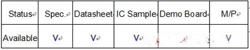
Product message
Pulse Group Suppression Filters
EMI Filters,Pulse Group Suppression Filters,Pulse Group Interference,Pulse Group EMI Filters
Jinan Filtemc Electronic Equipment Co., Ltd. , https://www.chinaemifilter.com