Optocouplers are compact in size, have a long service life, and can operate across a wide temperature range. They also offer strong resistance to electrical interference. Since they have no physical contacts and provide complete electrical isolation between input and output, they are widely used in various electronic devices. Optocouplers find applications in isolation circuits, load interfaces, and household appliances. Below are some of the most common application examples.
1. **Switching Circuit Construction**
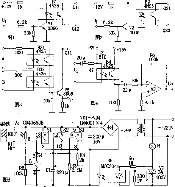
In the circuit shown in Figure 1, when the input signal ui is low, transistor V1 is off, causing the LED in photocoupler B1 to emit almost no current. As a result, the resistance between Q11 and Q12 becomes very high, effectively turning the switch "off." When ui is high, V1 turns on, activating the LED in B1, which reduces the resistance between Q11 and Q12, simulating a "closed" switch. This means that when the input is low, the switch remains open, allowing high-level conduction. In Figure 2, the switch is normally on when there's no signal (ui is low), meaning it operates in a low-level on state.

*Optocoupler application set*
2. **Logic Gate Construction**
Figure 3 shows an AND gate logic circuit, with the logical expression P = A · B. The two photo-sensitive tubes are connected in series, so the output P is high only when both inputs A and B are high. Similarly, OR gates, NAND gates, and other logic circuits can be constructed using optocouplers.
3. **Isolation Coupling Circuit**
Figure 4 illustrates a typical AC-coupled amplifier circuit. By selecting an appropriate current-limiting resistor Rl for the light-emitting diode, the current transfer ratio of B4 can be kept constant, ensuring linear amplification within the circuit.
4. **High Voltage Regulator Circuit**
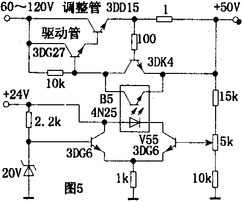
As shown in Figure 5, the drive transistor must have a higher voltage rating (e.g., 3DG27 in the diagram). When the output voltage increases, the bias voltage of V55 rises, increasing the forward current of the LED in B5. This causes the voltage across the phototransistor to drop, reducing the bias voltage of the adjustment transistor and increasing its internal resistance, thus stabilizing the output voltage.

*Photocoupler constitutes a high voltage regulator circuit*
5. **Hallway Lighting Automatic Control Circuit**
Figure 6 shows a circuit that automatically controls hallway lighting. A consists of four analog electronic switches (S1–S4): S1, S2, and S3 are connected in parallel to increase driving power and anti-interference capability. When powered on, the circuit drives a bidirectional thyristor VT through R4 and B6, which directly controls the hall lighting H. S4 and an external photoresistor Rl form an ambient light detection circuit. When the door is closed, the normally closed reed switch KD is magnetically activated, opening the contact. At night, when the owner opens the door, the magnet moves away from KD, closing the contact. This allows the 9V power supply to charge capacitor C1 through R1. The voltage on C1 quickly rises to 9V, triggering the LED in B6 via S1, S2, S3, and R4, which activates the thyristor VT and lights up H. After the door closes, the magnet disconnects KD, stopping the charging of C1. C1 then discharges through R3. After a delay, the voltage on C1 drops below the threshold of S1, S2, and S3 (1.5V), turning them off. This cuts off B6 and VT, turning off the light and achieving a delayed shut-off function.
LCD Interactive Whiteboard
LCD Interactive Whiteboard,Interactive Intelligent Panel,Smart Interactive Flat Panel,
Shanghai Really Technology Co.,Ltd , https://www.really-led.com