Tantalum capacitor anode selection
A common trend in switching power supplies, microprocessors and digital circuit applications is to reduce noise during high-frequency operation. In order to do this, components must have low ESR (resistivity), high capacitance, and high reliability.
The total surface area of ​​the anode of the tantalum capacitor, especially its surface area to volume ratio, is one of the key parameters to determine its ESR value. The larger the total surface area, the larger the ESR value. The use of multiple anodes is one of the methods to greatly reduce the ESR value of tantalum capacitors. The method is to use multiple same electrode materials in a capacitor.
Conventional methods In high-life and high-reliability applications, conventional tantalum capacitors with manganese dioxide electrodes are still a common choice. Manganese dioxide technology can provide excellent field performance and environmental stability as well as high resistivity and thermal resistance in a wide voltage range, such as 2.5 to 50V. The device is designed to operate at temperatures above 125 ° C. However, the higher ESR of the manganese dioxide electrode system is a disadvantage compared to polymer tantalum capacitors.
Anode selection Single anode technology has become the standard universal choice due to its excellent cost performance. The multi-anode design can provide a lower ESR value, but its disadvantage is that the production cost is higher than the single-anode solution.
The trough anode design using standard chip integration process is a result of low ESR and low cost compromise. Therefore, the trough design is usually used for price-sensitive designs that require low ESR, and multi-anode technology is suitable for applications that require both low ESR and high reliability, such as telecommunications infrastructure, networks, servers, and military / aerospace And other applications.
In addition to the above differences, the concept of multiple anodes has two other advantages.
(1) The multi-anode design has better heat dissipation performance, which means that the multi-anode capacitor can carry a higher continuous current; similarly, the multi-anode capacitor has a stronger ability to resist the harm of current surges.
(2) Compared with a single anode, the multi-anode capacitance has lower unit volume efficiency, which leads to the assumption that multiple anodes cannot achieve the same CV (constant voltage factor) as a single anode. In fact, thin anodes are easier to implement and more easily penetrated by the second manganese dioxide electrode system, allowing higher CVs to be utilized, so multi-anode capacitors can achieve the same or even higher CV levels.
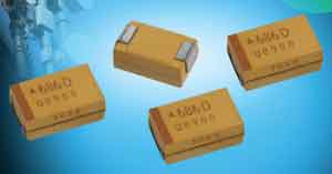
Common multi-anode types Tantalum multi-anodes commonly used in the market today are usually implemented by vertically arranging 3 to 5 anodes in a capacitor body, as shown in Figure 1. This is actually from a manufacturing point of view. If viewed from an ESR point of view, this solution is not as good as a horizontal layout. The thinner flat anode in the horizontal layout is expected to further reduce ESR.
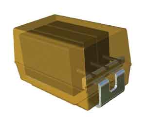
Figure 1 Multi-anode device uses two or more anodes in a capacitor body
The cost of the new multi-anode device multi-anode design increases exponentially with the number of anodes. The current three-anode design used in most designs is close to the optimal ratio of cost to ESR.
In the vertically designed structure, one anode is connected to the second through the electrode silver glue epoxy resin, and then to the other electrode lead frame. The same method is used in the standard single anode capacitor, so its manufacturing technology is similar to the old one, and there is no need to add a lot of additional investment for the new technology link of multi-anode design.
On the other hand, the lateral design requires a new solution for the connection between the anodes, which directly leads to costly technical modifications. Therefore, so far this design has not been used for mass production of single multi-anode capacitors. Lateral designs are more often used in special applications by welding or jigging systems to stack two or more complete capacitors into an array or module.
The difference between the ESR performance of the horizontal and vertical structures is shown in Figure 2. This example is based on theoretical calculations for Class D capacitors. Figure 2 shows that the ESR values ​​of the two-anode lateral structure and the three-anode system longitudinal structure are similar. However, relatively speaking, the horizontal structure has more significant cost-effective advantages in ESR.
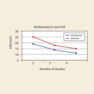
Figure 2 The performance of horizontal and vertical structures is similar, and cost becomes the determining factor
Compared with the horizontal structure, the vertical design is more restricted in reducing the height. The current height of the capacitor is generally 3.5 to 4.5 mm. Today, this factor is even more important. Even in applications such as telecommunications infrastructure and military, the miniaturization of electronic products is becoming a test, which was unprecedented in the past.
Using the lateral "mirror" structure of the two anodes, researchers have developed a new type of multi-anode structure. The mirrored structure uses a modified lead frame shape with the lead frame positioned between the two anodes. This structure solves the connection problem of the horizontal arrangement of the electrodes, and reduces the cost of process modification to an acceptable level.
The ESR performance of the two-anode mirror design is slightly inferior to that of the three-anode longitudinal structure, but it is cheaper to manufacture. The main benefit of the mirror design is that it reduces the height of the multi-anode capacitor, and the lowest drop is 3.1mm.
The other advantage of using mirror design is that its symmetrical layout helps reduce self-inductance (ESL). The symmetrical structure partially compensates the inductance loop, which is beneficial to reduce the ESL below the scheme using the classic lead frame design.
The ESL value of a Class D single anode design is 2.4nH, with a typical value of around 2.1nH. The ESL value of the mirror design is about 1nH, which is half that of the conventional design. This will raise the resonance frequency of the mirrored multi-anode to a higher value, as shown in Figure 3.

Figure 3 The performance of the mirror design (a) shows that its capacitance decreases with frequency lower than the single anode solution, and its (b) ESR value is also the same
If a thinner anode is used for the mirror structure, the capacitance will drop to lower with frequency. The reason why the resonance frequency of the mirror design changes is that the working range of the switching frequency (250 to 500 kH) of the current general DC / DC converter will be significantly increased by lowering the ESL.
Another benefit of the mirror design is to improve its heat dissipation performance. As shown in Figure 4, the heat generated by the ripple current at the anode is dissipated and cooled by the leads and tantalum wire on the PCB board.
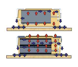
Figure 4 Mirror design (a) Compared with single anode device, the power consumption is improved
Therefore, although a single anode Class D capacitor can continuously dissipate only 150mW, a similarly sized mirror structure capacitor can handle 255mW. The current achievable capacitance value of mirror horizontal multi-anode capacitor is 220 ~ 1000μF, voltage is 2.5 ~ 10V, and ESR value is 25 ~ 35mΩ. Future developments will further expand the voltage range to 35 and 50V, which will make capacitors very attractive in new telecommunications applications where the design is becoming increasingly important. A single 35 to 50V capacitor has a capacitance of 10 to 22μF and a ESR value of 65 to 140mΩ within a maximum height of 3.1mm, which is difficult for any other technology.
Automotive Fuse
Automotive Fuse, ie Car Fuse , is the name we are often called. Its official name is "fuse protector." The use of Automotive Fuse Block is very similar to that of household fuses, which act as a circuit protection barrier when the circuit current is abnormal and exceeds its rated current. Vehicle fuses are broadly divided into two types of fast-blow fuses and slow-blow fuses.

A car is made of Car Fuse, Automotive Switches and other kinds of Automotive Accessories, and the Automotive Switches including Automotive Rotary Switches, Automotive Battery Switches, Automotive Rocker Switches

Inline Fuse Holder include high-current fuses and medium-low current fuses. Medium and low current fuses are generally easier to reach. Low-to-medium current fuses can be broadly classified as chip fuses (including automatic fuse box mini-fuse), plug-in fuses, screw-on fuses, and tube fuse box fuses. Among them, we are able to access medium-sized ATO or small-size fast-acting chip fuses. Chip fuses can carry small currents, short pulse currents, such as headlamp circuits, post-glass defrosting, and more.
Automotive Fuse
Car Fuse,Automotive Fuse,Automotive Mini Fuses,Automotive Fuses Types
YESWITCH ELECTRONICS CO., LTD. , https://www.yeswitches.com