PT2262 / PT2272 codec integrated circuit principle description
PT2262 / 2272 codec integrated circuit principle introduction
Introduction of codec chip PT2262 / PT2272 chip principle PT2262 / 2272 is a low-power low-cost general-purpose codec circuit manufactured by Taiwan Pucheng Company, which is manufactured by CMOS process. State address terminal pins (floating, connected to high level, low level), any combination can provide 531441 address code, PT2262 can have up to 6 bits (D0-D5) data terminal pins, set address code and data The code is serially output from pin 17 and can be used for wireless remote control transmission circuits. The encoding signal sent by the encoding chip PT2262 is composed of: address code, data code, and synchronization code to form a complete code word. After the decoding chip PT2272 receives the signal, the VT pin outputs high level after the address code is compared and checked twice. At the same time, the corresponding data pin also outputs a high level. If the sender keeps pressing the button, the encoding chip will continuously transmit. When the transmitter is not pressed, the PT2262 is not connected to the power supply, and its 17-pin is low, so the 315MHz high-frequency transmission circuit does not work. When a button is pressed, the PT2262 is powered and its 17th pin is output The modulated serial data signal, when 17 feet are high, the 315MHz high-frequency transmission circuit starts to oscillate and emits equal amplitude high-frequency signals, when 17 feet is low, the 315MHz high-frequency transmission circuit stops oscillating, so the high The frequency transmitting circuit completely receives and controls the digital signal output from pin 17 of PT2262, thus completing amplitude keying (ASK modulation) of the high-frequency circuit is equivalent to an amplitude modulation with a modulation degree of 100%.
Features of PT2262 1. CMOS process manufacturing, low power consumption 2. Less external components 3. RC oscillation resistance 4. Wide operating voltage range: 2.6-15v
5. Data can be up to 6 digits 6. Address code can be up to 531,441 kinds of applications 1. Vehicle anti-theft system 2. Home anti-theft system 3. Remote control toys 4. Other electrical appliances remote control 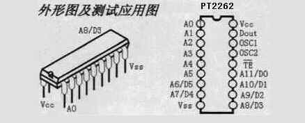
| name | Pin | Explanation |
| A0-A11 | 1-8, 10-13 | Address pins, used for address coding, can be set to "0", "1", "f" (floating), |
| D0-D5 | 7-8, 10-13 | One of the data input terminals is "1", that is, the code is sent out, and the internal pull-down |
| Vcc | 18 | Positive end of power supply (+) |
| Vss | 9 | Power negative terminal (ï¼) |
| TE | 14 | Encoding start end, used for encoding transmission of multiple data, low level effective; |
| OSC1 | 16 | Oscillation resistance input terminal, the resistance connected with OSC2 determines the oscillation frequency; |
| OSC2 | 15 | Oscillation resistance oscillator output; |
| Dout | 17 | Encoding output (low level when normal) |
In specific applications, the external oscillation resistance can be adjusted appropriately according to needs.
The larger the resistance value, the slower the oscillation frequency, the larger the encoding width, and the longer the time to send one frame.
Most products on the website are combined with 2262 / 1.2M = 2272 / 200K,
For a small number of products, 2262 / 4.7M = 2272 / 820K.


| name | Pin | Explanation |
| A0-A11 | 1-8, 10-13 | Address pin, used for address coding, can be set to "0", "1", "f" (floating), must be consistent with 2262, otherwise it will not be decoded |
| D0-D5 | 7-8, 10-13 | Address or data pin, when used as a data pin, only when the address code is consistent with 2262, the data pin can output the high level corresponding to the 2262 data terminal, otherwise the output is low, the latch type The next data can be converted |
| Vcc | 18 | Positive end of power supply (+) |
| Vss | 9 | Power negative terminal (ï¼) |
| DIN | 14 | Data signal input terminal, from the output terminal of the receiving module |
| OSC1 | 16 | Oscillation resistance input terminal, the resistance connected with OSC2 determines the oscillation frequency; |
| OSC2 | 15 | Oscillation resistance oscillator output; |
| VT | 17 | Decoding validates the output (normally low) decoding effectively becomes high (transient) |


Both address code and data code are represented by pulses with different widths, and two narrow pulses represent "0";
Two wide pulses represent "1"; a narrow pulse and a wide pulse represent "F" which is "floating" of the address code. 
The above is a section of the waveform that we intercepted from the signal output pin of the super regenerative receiving module.
The upper part of the figure is a group of word codes, each group of words is separated by a synchronization code, so if we use MCU software to decode, the program only needs to determine the synchronization code, and then the pulse width of the following words Just identify.
The lower part of the figure is an enlarged set of word codes: a word code consists of a 12-bit AD code (address code plus data code,
For example, 8-bit address code plus 4-bit data code), each AD bit is represented by two pulses:
Two narrow pulses represent "0"; two wide pulses represent "1";
A narrow pulse and a wide pulse indicate "F" which is "floating" of the address code
Each time 2262 transmits at least 4 sets of word codes, 2272 will only drive the corresponding data output terminal to high level and drive VT terminal if the same address code plus data code is detected twice in succession Synchronization is high.
Because of the characteristics of wireless transmission, the first group of codes is very susceptible to zero-level interference and often generates bit errors.
So the program can be discarded.


The PT2272 decoder chip has different suffixes, indicating different functions, which are divided into L4 / M4 / L6 / M6,
Where L represents the latch output, as long as the data is successfully received, it can always maintain the corresponding level state,
Until the remote control data changes next time. M means non-latching output,
The output level of the data pin is instantaneous and corresponds to whether the transmitter is transmitting, and can be used for similar jog control. The suffixes 6 and 4 indicate that there are several parallel control channels,
When using 4-channel parallel data (PT2272-M4), the corresponding address code should be 8 bits,
If 6-channel parallel data is used (PT2272-M6), the corresponding address code should be 6 bits.
Address coding setting and modification of PT2262 / 2272 chip:
In normal use, we generally use 8-bit address code and 4-bit data code. At this time, the first to eighth pins of coding circuit PT2262 and decoding PT2272 are address setting pins. There are three states to choose from: floating, connected to positive power 〠Ground three states, 3 to the 8th power is 6561, so the address code is not repeated for 6561 groups, only the address code of the transmitter PT2262 and the receiver PT2272 can be paired, the remote control module manufacturer in order to facilitate production management,
The eight-bit address coding terminals of PT2262 and PT2272 of the remote control module are left floating at the factory,
In this way, the user can easily select various encoding states. If the user wants to change the address encoding,
As long as the 1-8 pins of PT2262 and PT2272 are set the same,
For example, the first pin of the PT2262 of the transmitter is grounded and the fifth pin is connected to the positive power supply, and the other pins are left floating.
So as long as the PT2272 of the receiver is also connected to the positive power supply at the first pin and the fifth pin,
The other pins can be suspended to achieve paired reception. When the address codes of the two are completely consistent, the corresponding D1 to D4 terminals of the receiver output about 4V interlock high-level control signals, and the VT terminal also outputs a decoded effective high-level signal.
Users can amplify these signals by one level, and then they can drive relays, power transistors, etc. to carry out remote control of the load.
The address coding area is generally reserved on the remote control products provided on our website, and the method of soldering lap welding is used to select:
It is suspended, connected to the positive power supply, and grounded. The factory is generally suspended.
It is convenient for customers to modify their own address codes. Here we take the commonly used jumper area of ​​the super-regenerative pin-type receiving board A-L4 as an example:

Netizens can see that the jumper area is composed of three rows of pads, the eight pads in the middle are the first to eighth pins of the PT2272 decoder chip, and the one on the left is the first pin of the chip, the top one The pad on the row is marked with L, indicating that it is together with the power supply ground.If it is measured with a multimeter, it will be found with the 9th pin of PT2272; the bottom row of pads is marked with H, indicating that it is together with positive power
If you measure it with a multimeter, you will find it together with the 18th pin of PT2272. The so-called setting address code is to use solder to short-circuit the upper and lower adjacent pads with a solder bridge. After that, it is equivalent to setting the first pin of the PT2272 chip to ground. Similarly, short-circuiting the first pin and the lower pad H with solder is equivalent to setting the first pin of the PT2272 chip to a positive power supply. If it is not connected, it means floating.
The principle of setting the address code is: the same system address code must be consistent;
Different systems can be distinguished by different address codes. As for what kind of address code is set, it is completely up to the customer.
In addition to the address codes of PT2262 and PT2272, the oscillation resistance must also match,
Otherwise, the receiving distance will become shorter or even impossible to receive. With the development of technology, a number of compatible chips appear on the market.
In actual use, as long as the oscillation resistance is slightly modified, it can be used together. According to the actual use experience of our website,
The following parameters match better:
Code transmitter chip | Code receiving chip | |||||
PT2262 | PT2260 | SC2260 | SC2262 | CS5211 | PT2272 / SC2272 / CS5212 | |
1.2M | no | 3.3M | 1.1M | 1.3M | 200K | |
1.5M | no | 4.3M | 1.4M | 1.6M | 270K | |
2.2M | no | 6.2M | 2M | 2.4M | 390K | |
3.3M | no | 9.1M | 3M | 3.6M | 680K | |
4.7M | 1.2M | 12M | 4.3M | 5.1M | 820K | |
2262 IR is a 2262 series dedicated chip for infrared remote control, you can wire according to the following drawings
The receiving distance can be adjusted by adjusting the size of the Rosc resistor at the transmitting end, and the adjusting range of the transmitting end resistance is 390 to 420K.


SC series chips fully compatible with PT2262 / 2272 chips, this chip can directly replace PT series chips,
No need to make any changes to the periphery, but the price is much cheaper than the PT series 
As a switch supplier,most of our products compliance with TUV,CE approval which based on EN 61058-1;2002+A2,the current rating from 10amp to 16amp,Ranging from 3 to 6 poles,with many choices of functions.Including series KR1,KR2 and KRX.Different size of the panel cut-out,kinds of functions for different application.
For example,the following item KRX meet TUV/CE requirment at 2A 250VAC:

TUV Approved Switch,Professional TUV Approved Switch,safety TUV Approved Switch
Ningbo Kara Electronic Co.,Ltd. , https://www.kara-switch.com