Principle and maintenance of BGTV4152 all-solid-state TV transmitter
Principle and maintenance of BGTV4152 all-solid-state TV transmitter
0 Preface
BGTV4152 all-solid-state TV transmitter is a new type of transmitter produced by Beiguang Technology Co., Ltd. Shanxi Radio and Television Wireless Management Center put into use four of these transmitters in four directly affiliated Gaoshan stations in 2007. After nearly two years of operation, the transmitter is stable, safe and reliable. Ensure the safe and high-quality broadcast and effective coverage of the launch pad.
1 Working principle
1.1 Basic composition and working principle
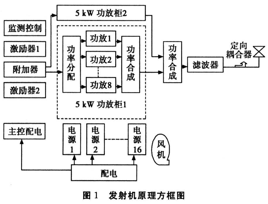
BGTV4152 all solid-state TV transmitter adopts modular design, advanced technology, complete interface, high index quality, stable performance and easy maintenance. The transmitter is mainly composed of 8 parts: an exciter, a power distributor, a power amplification module, a power synthesizer, a control system, a filter, a cooling system, and a power supply (as shown in Figure 1).
The video and audio signals from the signal source are sent to the TV exciter to form a composite radio frequency signal. The transmitter uses a dual exciter configuration. Automatically switch the dual exciters through the adder, and distribute the output signals of the exciter into two channels, which are sent to two 5 kW power amplifier cabinets. The power divider divides the high-frequency signal from the exciter into 8 channels and sends it to the power amplifier unit. After the high-frequency signal is amplified by the power amplifier unit, it uses power synthesis technology to output 5 kW of RF power. Then the high-frequency signals of two 5 kW power amplifier cabinets are combined into one, so that the final stage outputs 10 kW of synchronous top power. Finally, it is output to the antenna system through the filter and the directional coupler.
1.2 Working principle and technical characteristics of each functional module
1.2.1 Exciter
The exciter is an important part of the transmitter. It is a functional part of the transmitter that performs video and audio signal processing and is modulated into a radio frequency signal. Its performance determines the performance index of the transmitter.
The video signal sent from the signal source is processed by amplification, delay, clamping, white level limiting, synchronous regeneration, etc., and then sent to the image intermediate frequency modulator for amplitude modulation. The amplitude modulated image intermediate frequency signal passes through the surface acoustic wave filter to form a residual After the sideband is output to the IF corrector, the audio signal is sent to the audio circuit. After pre-emphasis and filter amplification, it is sent to the sound IF modulator to adjust the frequency, and the IF signal that has been adjusted to the sound is also output to the IF corrector. The IF image modulated signal is corrected by DG, low frequency non-linear distortion correction and frequency response adjustment, etc., and combined with the sound IF signal in the small box of the IF corrector to form a composite TV IF signal with an image sound power ratio of 10: 1. The TV intermediate frequency signal is sent to the up-converter after the intermediate frequency correction, intermodulation correction, group delay correction, DP correction, and ICPM correction to become a radio frequency signal and filter out-of-band clutter. It is sent to the amplifier and amplified to 160 mW output. There is an ALC automatic level control circuit in the exciter, which makes the output power of the exciter very stable. In addition to the stable power, there are two protection functions: First, once the video signal is interrupted, the image carrier remains at the black level amplitude, and will not be pulled to the synchronous top level by the peak detection AGC in the corrector. Amplifier overload. Second, there is a "soft start" function. When the power is turned on or the radio frequency signal is turned on and off, the amplitude of the radio frequency signal is always small and then slowly started, to avoid the impact on the post-stage power amplifier.
1.2.2 Power splitter
The transmitter is power synthesized by two 5 kW power amplifier cabinets and outputs RF10 kW. Each 5 kW power amplifier cabinet is composed of 8 750 W high power amplifier units. The power divider divides the signal output by the exciter into 8 outputs and sends it to the RF power amplifier for amplification. In addition to the signal distribution, the power divider also plays a role in matching between the front and back modules.
1.2.3 Power amplifier module
The power amplifier module uses LDMOS devices for power synthesis, with an output power of 750 W. Its main features are:
(1) Imported MOSFET BLF368 is used for power amplification in the unit. The gain is high, the linearity is good, it can operate under higher reflected power, and it has better temperature characteristics, and the temperature coefficient is negative;
(2) The output end of the power amplifier tube is connected with a high-power circulator. When the output of the power amplifier is open, the power amplifier tube is not easy to be damaged; it is easy to maintain;
(3) Hot plugging is allowed;
(4) Perfect working status detection function. Not only provide the switch state and analog value of the working state and fault signal to the transmitter microcomputer control system; also provide the working state detection interface on the front panel;
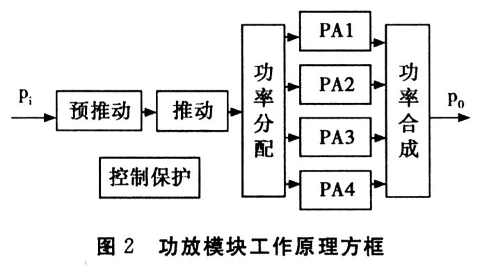
(5) The phase fine-tuning circuit ensures accurate power synthesis and reduces synthesis loss. The block diagram of the working principle of the power amplifier module is shown in Figure 2.
The power amplifier is composed of a three-stage power amplifier, using power synthesis technology, and the total gain is about 40 dB. The first stage of the power amplifier consists of a broadband power amplifier module and two Class A power amplifier tubes. The distribution and synthesis use 3 dB coupling lines to achieve a good match between the input and output ends. Has a very high linear index. The second stage pushes the power amplifier to use two BLF368 power tubes, working in Class A. The BLF368 power amplifier tube is a push-pull tube, which requires balanced input and output. The input / output of this circuit uses balanced semi-hard coaxial cable to realize balanced / unbalanced conversion, so that the input and output of the power amplifier tube can be matched. Class A amplifiers have good linear indicators and a large dynamic range, laying a good foundation for digital TV. The last stage power amplifier uses the same type of LDMOS power tube as the second stage, sharing 4 syntheses. Working in class AB, the combined output power is 750W. The first-level second synthesis uses stripline orthogonal bridge synthesis, the second-level and third-level uses the same direction synthesis; the corresponding distribution network first-level and second-level uses the same-phase distributor. The balanced / unbalanced conversion is also used to achieve matching at the input and output ends of each tube.
Each power amplifier module is equipped with an independent switching power supply.
Each power amplifier module is equipped with protection facilities such as over-excitation, over-heat, overload, over-voltage, over-reflection protection, etc., and the work is stable and reliable.
1.2.4 Power combiner
After the high-frequency signal is amplified by the power amplifier unit, the power synthesis technology is used to synthesize the high-frequency signals of several power amplifiers into one, so that the final stage output meets the required synchronous top power. It consists of a passive network and is equipped with absorption resistors. When the output power of each power amplifier is unbalanced, they are balanced by absorption.
1.2.5 Harmonic filter
The harmonic filter is used to suppress one or more harmonic components, so that the out-of-band harmonic components meet the requirements of the index.
1.2.6 Directional coupler
The output directional coupler detects the incident wave and reflected wave of the output signal and feeds it back to the control system as a power indication and fault detection signal.
1.2.7 Monitoring of the transmitter
This transmitter has two sets of control, protection, and detection systems. One set is a microcomputer monitoring system, which can realize manual / automatic on and off procedures and can monitor output power, reflected power, current, temperature and other parameters of tubes in each power amplifier module. Realize fault detection and alarm, record and print. It can also be equipped with a PC for remote control and remote operation of the transmitter. The system also records the historical status information of the transmitter and stores it in a data table file for users to view when needed, which is convenient for the management of the computer room and the system, as well as the maintenance of the transmitter; the other is the traditional switch control, which is a microcomputer. Controlled backup. It can also realize the on-off operation.
2 Use and maintenance of the transmitter
2.1 Normal transmitter operating procedures
2.1.1 Check before starting
After the first installation or maintenance, the machine should be checked before starting up. First check whether the power supply and safety ground wire are correct; check whether all RF connecting cables are connected and connected firmly; check whether the ventilation system is normal; especially connect the load or antenna feeder of the image output end. In short, you should check the system wiring is correct before starting.
2.1.2 Start-up steps
First connect the three-phase 380 V power supply to the machine correctly. Before starting the machine, first place the air switch QT in the "off" position, and then determine whether the 380 V voltage is normal. Then place QT in the "closed" position. At this time, the + 24V / + 12V regulated power supply in the exciter works, the monitoring unit sends power, and the whole machine is in the state of being turned on. The exciter works normally.
Under the condition that no video signal or audio signal is fed in, the "video alarm" in the image modulator lights up in red, and the audio modulator's "audio" lights up in red. The test meter installed on the front panel of the exciter has no indicated value. The frequency deviation test meter on the front panel of the exciter also has no frequency deviation display. If both the video signal and the audio signal are sent to the IF modulation box, the red light of the "video alarm" in the image modulator is off, the green light of the "output" is on, the red light of the audio modulator is off, and the front panel of the exciter is installed. The meters have indication values, indicating the modulation degree (about 87.5%) and frequency deviation (about 50 kHz).
Press the start button and observe whether the rotation of each fan is normal and whether there is any abnormal sound. Whether the 32 V DC stabilized power supply and 750W power amplifier module work normally, and the power reaches the normal value after a few seconds.
After the above operation steps are completed, the machine enters the normal working state. Press the output power button. Looking at the power meter above the LCD screen of the machine indicates that the output power is 10 000W synchronous top. Press the reflection output button. The meter indication is very small, indicating that the antenna feeder system is normal. Use the TV receiver to watch the effect in the computer room. If the picture and sound are good, it means the machine is working normally.
2.1.3 Steps to shut down the transmitter
Press the shutdown button, the power meter has no indication value, the indicator light of the power amplifier module is not on, the fan stops blowing and cooling, and the 32 V DC stabilized power supply does not work. Finally cut off the 380 V power supply for this machine.
2.2 Use and maintenance
In order to ensure the safe operation of the machine, prevent machine failure and component damage, and at the same time ensure the safety of the check-in staff, attention should be paid to the following aspects.
(1) The ambient temperature and air volume for normal operation of the transmitter should be guaranteed, and dust cleaning and main index testing should be carried out regularly.
(2) Due to vibration factors such as blowing, the fasteners can be loosened, and regular inspection and reinforcement should be carried out.
(3) During the operation of the machine, it is not allowed to easily pull out the power amplifier box or disconnect the high-frequency cable connection line, otherwise it will make the work abnormal and even cause partial damage to the equipment.
(4) Maintenance records should be carefully maintained to help prevent hidden troubles and analyze equipment failures.
(5) Be sure to connect the antenna feeder system to ensure a good match (standing wave ratio is less than 1.2).
(6) When operating the field effect tube, anti-static measures must be taken.
3 Conclusion
After more than two years of operation, the transmitter performance is stable and no major faults have occurred. The system indicators have also reached the level A standard issued by the Ministry, and the wireless coverage effect is good in each coverage area. All-solid-state transmitters have obvious advantages such as cost savings, small maintenance, safety and reliability, but the technical requirements for technical personnel in use and maintenance are greatly improved, and more standardized operating procedures and maintenance management systems are required. We usually strengthen business learning , Summarize the maintenance experience in time, ensure the correct maintenance and operation of the transmitter, and ensure the safe and high quality broadcast.
LC Fiber Connector provides a pull-proof design and small size perfect for high-density applications. A series of Fiber Connector LC is Single Mode LC Connector and multimode LC Connector ,simplex and duplex Fiber Optic LC Connector with different diameters (0.9mm,2.0mm,3.0mm). The LC fiber connector, which is provided with a 1.25mm zirconia ferrule, are widely used for Fiber to home(FTTH),Local Areal Networks(LAN),Passive Optical Networks(PON),CATV,Fiber communication system. Foclink,a reliable supplier of SC Fiber Connector is always beside u 7*24.
LC Fiber Connector
LC Fiber Connector,LC Connector,Fiber Optic LC Connector,Single Mode LC Connector
Foclink Co., Ltd , https://www.scfiberpigtail.com