Design of light source driver for handheld communication equipment
Design of light source driver for handheld communication equipment
The application of light sources in communication handheld devices is mainly reflected in three aspects: keyboard lights, LCD screen backlights and special lighting. The main light-emitting devices are semiconductor light-emitting diodes (LEDs), and the driving chip design technology includes low-dropout (LDO) regulators and adjustable (Regulator) regulated power supply, charge pump (Charge Pump) power supply and super capacitor (Super Capacitor) power supply in different forms.
Semiconductor light-emitting diodes (LEDs) have the characteristics of small size, power saving, long life and high reliability, and are widely used in screen display and information transmission prompts in communication handheld devices. At present, LEDs are developing towards high brightness, full color, high performance, and low cost.
Among the three modules of the light source of the handheld device, the application mode of the keyboard light is relatively fixed, usually 4 to 10 LEDs are used, and the current is limited by means of series resistance, and the overall power consumption is relatively small. With the different operating voltages, LEDs also undergo several changes in color. The earliest LEDs emit yellow-green backlights. The driving voltage of the chip is generally about 2.5V, and the GaP: N of yellow-green LEDs (nitrogen-doped epitaxy of LEDs) (Wafer) The luminous efficiency of the wafer is the highest, with a high intensity corresponding to the main peak of the luminescence band at yellow-green 591 nm. Later, high-intensity InGaN products with a quantum well structure appeared, enabling LEDs to emit mixed colors of green, blue, red, and purple-pink. This is the light source used in so-called "bright" mobile phones. The driving voltage of this type of LED is higher, usually between 3.8 and 4.1V. If the number of LEDs is the same, the power consumption of these colored lamps is higher than that of yellow-green lamps. Most keyboard lights now use high-brightness white LEDs, and some use less expensive yellow-green LEDs for cost reasons.
The screen backlight in the handheld device is an indispensable function. Since the screen itself has a black and white screen and a color screen, the requirements for the light source are also different. The LED used for the black and white screen can have the same power drive and color as the keyboard light, but for the larger black and white screen, the high brightness LED is used to give the light source from the side, and serious light will appear on the screen The phenomenon of uneven distribution, so people have developed the "Electro Luminescence" (EL: Electro Luminescence) backlight, its principle is mainly by applying a luminescent material on the surface of a transparent organic bottom plate or linear structure object, the two poles are connected to an AC voltage When an alternating electric field is generated, when a certain critical value is reached, the electrons excited by the electric field collide with the luminescent layer, causing the electron energy to jump, change, and recombine, which is a physical phenomenon that emits high-efficiency cold light. In practical applications, it has been found that EL light is soft, uniform, non-heating, consumes less power, and is thin, light, and easy to carry, but it is expensive.
When a color screen appears on the LCD, the main demand for the light source is white light, which is determined by the optical structure of the color LCD screen. The reason is that the white light must be uniformly distributed and directed by the polarizer to form the final image, and then passed The liquid crystal film that can form a color pattern, if it is other colors of light, can not make the liquid crystal film with RGB unit accurately display the color of the graphics. The number of LEDs required depends on the screen size and brightness requirements, generally 4 to 8, and in order to obtain a more consistent and uniform light output effect, these white LEDs are often connected in series, so they must be provided to enable them to work together Drive voltage at sufficient brightness current.
The special lighting requirements of communication handheld devices mainly include: colorful LED indicators, flashlight function and photo flash.
The colorful LED indicator is a transitional product between the appearance of the color screen and the appearance of the mobile phone camera. It mainly produces different optical effects by controlling the luminous time of three different LED chips of R, G and B. However, it is a failure in handheld devices, mainly because if you want to achieve the "dazzle" effect, once the colorful LED indicator is working, the system cannot enter the deep sleep state, which also consumes a lot of software and hardware resources of the system Large, coupled with the large power consumption of the LED, causes a short standby time and seems to outweigh the gains.
Flashlights and photo flashes are new features in mobile phones with more than one million pixel cameras. White LEDs provide a strong light source, and with the continuous expansion of mobile phone internal storage capacity (SD card, T-Flash card, etc.) PC data sharing, and the popularity of data transmission between networks (MGPRS (EGPRS / 3G)), users have higher and higher expectations for the quality of the photos they take, and they are required to provide flash in dark places. The flashlight function is actually an accessory function of the photo flash, and can share hardware resources with the photo flash. The earliest photo flash is not a real flash because it requires software to turn on the light in advance, and there is no programming interface to synchronize the photo process. Secondly, its LED current of about 200mA produces a very low brightness, and only It plays a limited role in the range of half a meter, which means that the flashlight function is the condition that the flash lamp continuously works in the small current mode. Similarly, both the LCD backlight and the keyboard backlight can be incorporated into an overall application solution.
Therefore, as long as there is a high-power, high-brightness light source driver, the light source demand of the handheld device can be completely solved.
It is roughly believed that if it is set to effectively fill the camera phone within two meters, the working current of the LED needs to reach 800mA to 1.5A to produce the required light intensity. There are also some devices that use two LEDs in parallel to increase the output light intensity in order to achieve the designed brightness. If you want to achieve the same fill light effect as the "xenon lamp" of a digital camera, you need an LED current of 4A. At the same time, the quality of the lighting effect also depends on the condenser lens effect, the light receiving area and the distance from the light source.
In short, in order to improve the user's experience, high-brightness white LEDs will be the first choice of light-emitting devices for light sources in handheld devices. It can be used in three aspects of keyboard lights, LCD screen backlights, and special lighting, and can be provided separately for each application. The power supply can also manage all light sources by multiple outputs of one driving device.
Analysis and comparison of light source drive implementation schemes
According to current market requirements, the light source driver chip should provide a large drive current output, can provide multiple outputs, and can also output a small current. Existing low-dropout (LDO) voltage regulators and adjustable regulated power supplies, although easy to integrate into the system, have too little drive capability to meet new requirements.
The relationship between the operating voltage and current of a typical high-brightness LED, and the relationship between LED brightness and current is shown in Figure 1. The effective operating voltage of lithium-ion batteries used in general handheld devices is about 3.0 to 4.2V. A single LED (or parallel), the voltage is somewhat too high and the efficiency is low, and the problem of insufficient voltage will occur when multiple LEDs are connected in series. Therefore, people have proposed a backlight driving chip that can provide relatively suitable driving voltage and current.
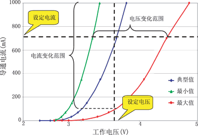
(a) LED operating characteristic curve
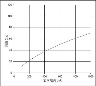
(B) The relationship between LED brightness and current
Figure 1 Typical LED operating characteristics and light efficiency
Secondly, the control methods of LED are mainly voltage control and current control, as shown in Figure 2.
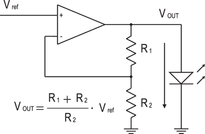
(A) LED voltage control principle
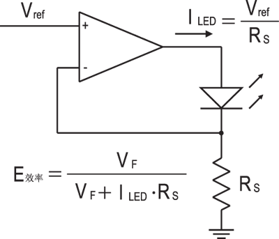
(B) LED current control principle
Figure 2 Commonly used control methods and working principles
The so-called voltage control refers to only need to drive the chip to provide rated voltage. Current control allows the output voltage to be adjusted as the load changes, and the operating current can be stabilized at a certain value according to the set requirements. Both methods require feedback detection. Reanalyze the operating characteristics of the LED shown in Figure 1 (a), whether it is set voltage to investigate current or fixed current analysis voltage, in fact, at the same current set point, it is necessary to cause the LED to produce a voltage fluctuation range of approximately the same brightness. Therefore, it is not recommended to use voltage control, and the use of current control obviously has the advantage that it can make the current independent of the driving voltage.
There are two common types of current control topologies: capacitive and inductive. Both structures can be controlled by pulse width modulation (PWM). The switching frequency is 30kHz to 2MHz. As the technology level of the device increases, the switch Speed ​​may also increase, and efficiency will be improved accordingly. With the improvement of LED design process technology, devices with higher power and high brightness can be manufactured, and corresponding large-capacitance structures are needed to meet the design performance and make up for the deficiencies of the previous two in driving capability.
The main energy storage element of the capacitive drive topology is a capacitor, which can produce an output voltage that is 1 times, 1.5 times, or 2 times the input according to the requirements of the load end. Figures 3 to 5 are their working principles.
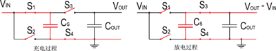
Fig. 3 Capacitive charging and discharging process with 1 times voltage
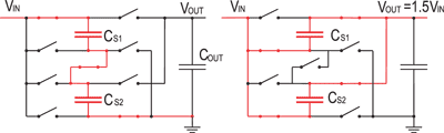
Fig. 4 Capacitive charging and discharging process with 1.5 times voltage
Fig. 5 Capacitive charging and discharging process with 2 times voltage
For the capacitive drive structure, according to the analysis of energy conservation, the current at the input will also change with the multiple relationship, that is, the current at the input is equal to the current at the output when the voltage is 1 times, and the current at the input is the current at the output when the voltage is 1.5 1.5 times, when the voltage is doubled, the input current is twice the output current. At the same time, the efficiency of this structure is calculated according to the voltage relationship, defined as:
Where M is the voltage change multiple. Figure 6 shows the change curve of the efficiency at these multiple times at different set currents. Assuming that the input voltage is 3.6V and the output voltage is 3.5V, if 2 times boost is used, the efficiency is only 50%, if 1.5 times boost, the efficiency is only 65%, and the efficiency of 1 times boost can reach more than 97% .
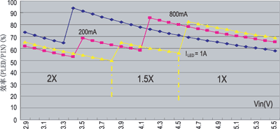
Figure 6 Simulation results of the efficiency of the capacitive structure
The main energy storage element of the inductive structure is an inductor. The output voltage can be linearly adjusted by controlling the duty cycle of charge and discharge within a cycle. Figure 7 shows a topology that can adaptively implement boost or buck. , Its working principle is: (1) S1 and S3 are closed, boost mode, the voltage across the inductor is equal to the input voltage; (2) S1 and S4 are closed, forward conduction mode, the voltage across the inductor is equal to the input voltage minus the output Voltage; (3) S2 and S4 are closed, buck mode, the voltage across the inductor is equal to the reverse output voltage.
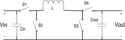
(A) Inductive structure
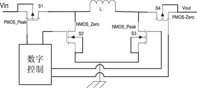
(B) Realization circuit of inductive structure
Figure 7 Topological structure and circuit for adaptively realizing boost or buck
Compared with the capacitive structure, the efficiency of the inductive structure is analyzed from the perspective of current. It is assumed to work at a switching frequency of 2MHz, in the buck mode from 2.5V to 1.2V, and the boost mode from 2.5V to 5V, each The internal resistance of a MOS tube is approximately 0.17Ω, then the efficiency curves obtained by simulation when different inductance values ​​are selected are shown in Figure 8 and Figure 9, respectively.
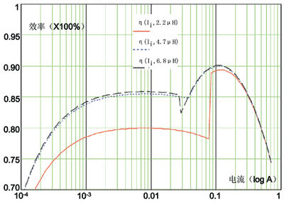
Figure 8 Simulation results of efficiency in buck mode from 2.5V to 1.2V
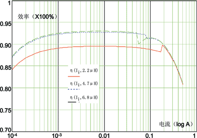
Figure 9 Simulation results of boost mode efficiency from 2.5V to 5V
According to the simulation results of boost and buck, when the switching frequency of 2MHz and the design internal resistance of the MOS tube are approximately 0.17Ω, the value range of the energy storage inductor can be less than 4.7μH, as can be seen from the figure In general, 2.2μH or even 1.5μH is acceptable under normal circumstances, which means that not only the cost is reduced, but also the layout space can be saved in the PCB design.
The supercapacitor mode is generated due to the limitations of the above two structures, because the maximum output current of the first two structures is limited by the battery specifications. If it is assumed that the operating current can reach 1A and the output voltage is twice the input voltage, according to the efficiency expression given above, assuming that the respective average efficiency can reach 80%, then the current mapped to the input can reach 2.5A, This will cause over-discharge and a large voltage drop, which is not allowed for lithium ion batteries. Therefore, when the current required by the input battery is greater than 2A or greater, the battery output current needs to be limited. Correspondingly, an energy storage capacitor is required at the load, and the capacitance value is generally 0.2F to 1F. Figure 10 is the definition based on this concept.
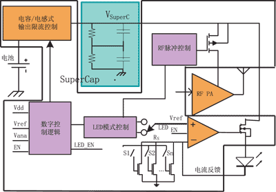
Figure 10 Block diagram of super large capacitor mode
For the working principle of this new structure, first charge the ultra-large capacitor through the current limiter designed by the capacitive or inductive structure. When the high-power consumption module, such as high-brightness LED and RF power amplifier, needs a very short time When a large driving current is working, the energy is mainly provided by an ultra-large capacitor. Of course, the limitation of this structure is that it still cannot work in a large current state for a long time. Figure 11 uses an inductive structure as a current limiter. Figure 10 is used. The shown current controls the charging of the super capacitor structure and a complete discharge and charging process. It can be seen from the charging process in the figure that under the control of the current limiter, the ultra-large capacitor obtains energy and the potential is improved, so that the driving ability is guaranteed; when fast discharge is required, the current limiter itself acts as a driving source together with the ultra-large capacitor To output energy to the load, the ultra-large capacitor is charged again to obtain energy after completing a working cycle. This maximizes the safety of the battery and the stability of the system.
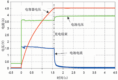
(A) Initial charging process of super large capacitor
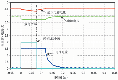
(B) Discharge and charge process within one cycle
Figure 11 Simulation of charging and discharging process of super large capacitor structure
By analyzing and comparing the above structures, it can be seen that the development trend of driver chips used in light sources of communication handheld devices will be small package, high power, programmable control, good thermal efficiency and reasonable cost, and will also try to The power driver is integrated in the system power management module.
A Hose Reel is a cylindrical spindle made of either metal, fiberglass, or plastic and is used for storing a hose. The most common styles of hose reels are spring driven (which is self retracting), hand crank, or motor driven. Hose reels are categorized by the diameter and length of the hose they hold, the pressure rating and the rewind method. Hose reels can either be fixed in a permanent location, or portable and attached to a truck, trailer, or cart.
Automatic hose reels for diesel and oil have been designed to ensure highefficiency.
The sturdy structure can guarantee best performance also in heavy duty conditions.
Thanks to its high volume design, this retractable diesel fuel hose reel is capable of dealing with environments where a longer length hose is required
Hose Reel
Hose Reel,Air Hose Reel,Water Hose Reel,Oil Hose Reel
NINGBO BEILUN TIAOYUE MACHINE CO., LTD. , https://www.spool-manufacturer.com