Signal control PLC program for two-speed elevator - News - Global IC Trade Starts Here.
First, the steps to prepare the plc elevator program
1. System design According to the method of determining the drag and control of the elevator and other special requirements, according to the unit and individual conditions, calculate the I/O points and select the specifications of the PC, and design and draw the circuit schematic and installation wiring diagram.
2, design PLC ladder program using PLC as the intermediate process control elevator electrical control, after the circuit schematic diagram and installation wiring diagram design is completed, you must also design and draw the PLC ladder program corresponding to the circuit schematic diagram, the ladder program is The logic control diagram of various soft and hard relays in PLC, its logic control mode is similar to the logic control circuit diagram between intermediate process control relays, so it is one of the important links in the design of PLC control electrical system. When designing the ladder program, it should be connected to the PLC manual manual to understand the PLC's I/O interface assignment, combination arrangement and code, various soft relays, data areas, channel codes, common rules and code names.
The ladder design should generally follow the following rules:
(1) The normally open and normally closed contacts of the I/O point and various internal soft relays can be reused many times.
(2) The coil of the soft relay cannot be directly connected to the busbar on the left, and there should be a transition point.
(3) There can be no more contacts on the right side of the soft relay.
(4) In a set of ladder diagrams, coils of the same code cannot be repeated. (with SET, RST instructions)
(5) The input and output points of the PLC can be used as soft relays.
3. After instilling the program in the PLC, the simulation operation must be performed first. The method can simulate various states of the input terminal by means of wiring, and watch whether the output signal meets the design requirements.
Programming software introduction We use Mitsubishi FX series PLC, you can use Mitsubishi FX series PLC special programming software FxGP/WIN to program. The software can be programmed in three ways: (1) input command mode (2) draw ladder mode (3) SFC programming mode. Use a dedicated cable SC-09 to communicate with the PLC for infusion or readout procedures. Moreover, it is possible to monitor the running PLC online and observe the operating states of various soft relays inside the PLC, which is very convenient to use.
Second, determine the number of I / O interface points, PLC selection Now we prepare a three-door three-station signal control two-speed elevator as an example, first calculate the required number of I / O interface points according to control requirements.
1. Input interface:
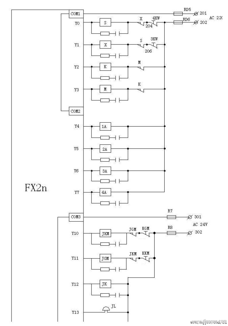
(1) Safety circuit (2) Door lock (3) Inspection switch (4) Upper level sensor (5) Lower level sensor (6) Up button (7) Down button (8) Close button (9) Open door Forced deceleration limit on button (10) (11) Forced deceleration limit (12) Elimination button (13) Lock ladder key (14) First floor sensor (15) Second floor floor sensor (16) Third floor Floor sensor (17) first floor command button (18) second floor command button (19) third floor command button (20) first floor up call button (21) second floor up call button (22) second floor down call button ( 23) 3rd floor down call button 2, output interface (1) Upstream contactor (2) Down contactor (3) Express contactor (4) Slow contactor (5) First stage acceleration contactor (6) First stage deceleration Contactor (7) secondary deceleration contactor (8) three-stage deceleration contactor above one group: contactor with alternating current 200V voltage (9) door opening relay
(10) Door closing relay (11) JK relay (12) Buzzer (13) Up direction display (14) Down direction display (15) First floor display (16) Second floor display (17) Third floor display (18) First floor command display (19) Second floor command display (20) Third floor command display (21) First floor call display (22) Second floor call display (23) Second floor second call display (24) Third floor The next call is displayed as a group: AC 24V voltage power supply is selected according to calculation, input a total of 23 points, output a total of 24 points, we can use FX2n-48MR PLC to program (input and output 24 points each).
Third, drawing schematic diagram and PLC installation wiring diagram 1, the main circuit 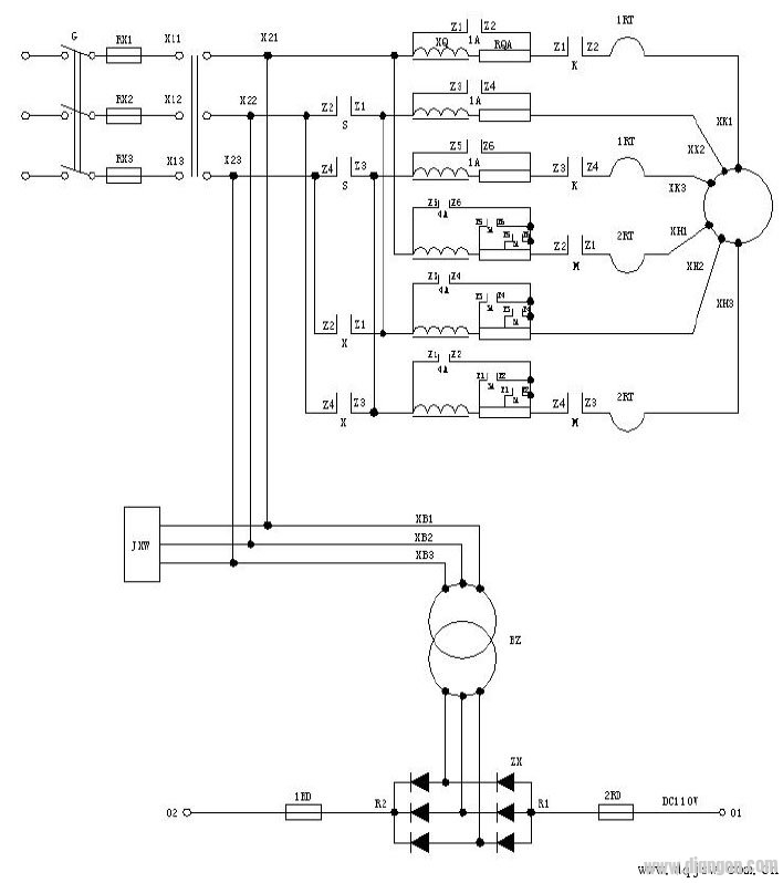
2. Safety circuit, door lock circuit, brake, door machine circuit 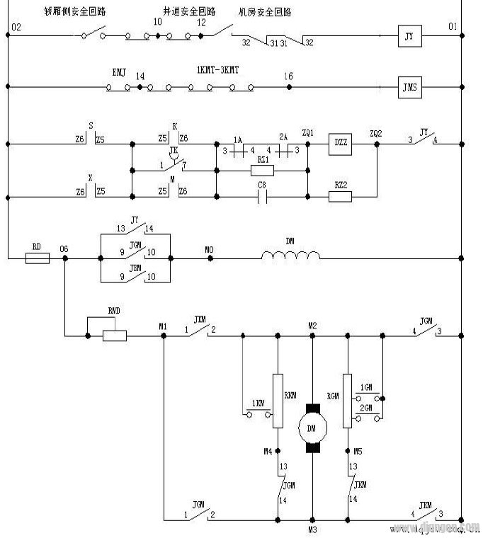
3, PLC wiring diagram (input loop) 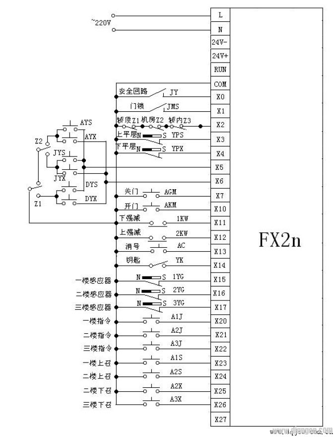
The line number and relay (contact) contact number in the figure can be customized according to the actual situation, and will not be drawn here. The other part of the power supply and the lighting part are also not shown.
4, floor control loop 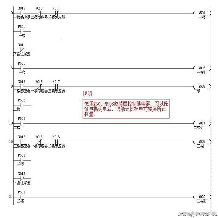
5. Registration and elimination of instructions and summoning signals 
6, automatic directional loop 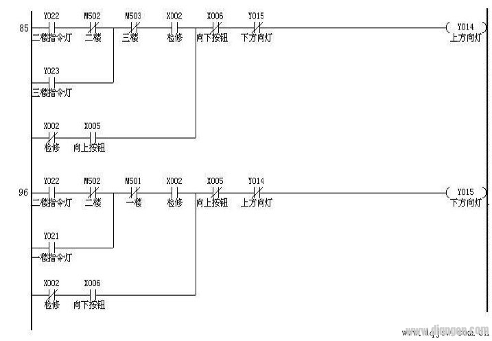
7, start closing and starting 
8, switch door relay 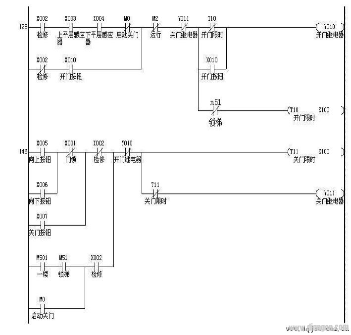
9, base station lock ladder 
10, up and down contactors, running relays 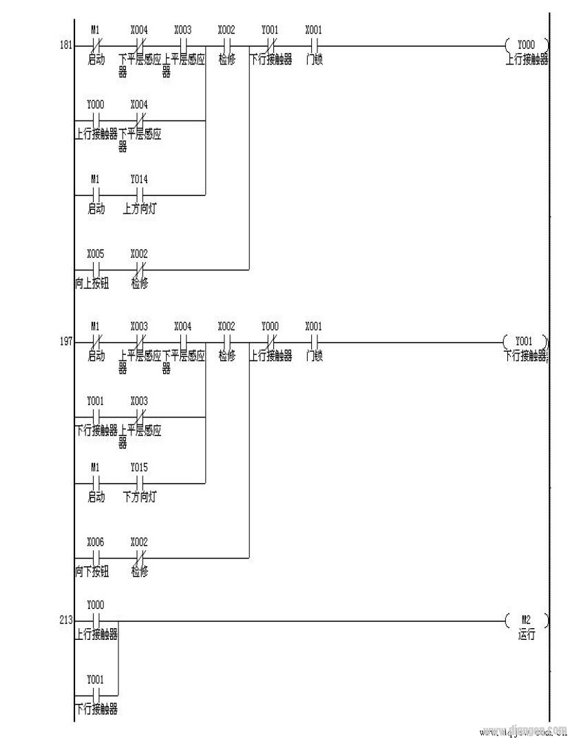
11, stop station trigger and stop 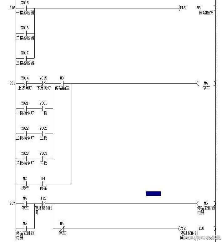
12, express, slow contactor, JK relay 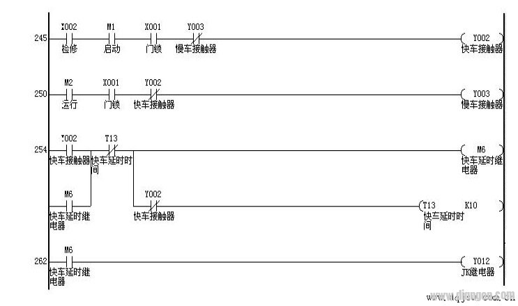
13, 1A, 2A, 3A, 4A contactors 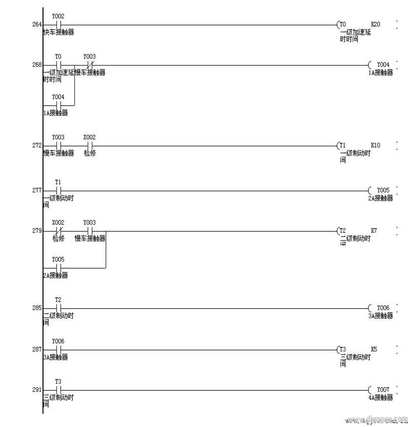
14, buzzer, end 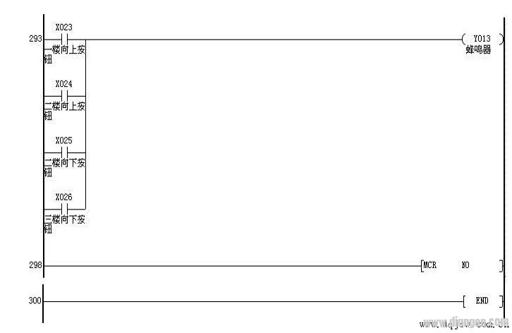
Fourth, the principle of using the up and down speed change switch to perform floor flipping In the traditional elevator circuit, the floor sensor is usually used to reverse the floor. In this way, at least one sensor should be installed on each floor in the hoistway, occupying a large number of input points of the PLC. Since the programming function of the PLC is very rich, it is possible to use the uplink speed change and the down speed change signal to perform the floor flipping, so that only two sensors on the side of the car are needed to realize the flipping and deceleration signals of the elevator floor. Issued, which brings convenience and cost savings to the installation.
The plc programming ladder diagram is shown below (four-layer elevator as an example) 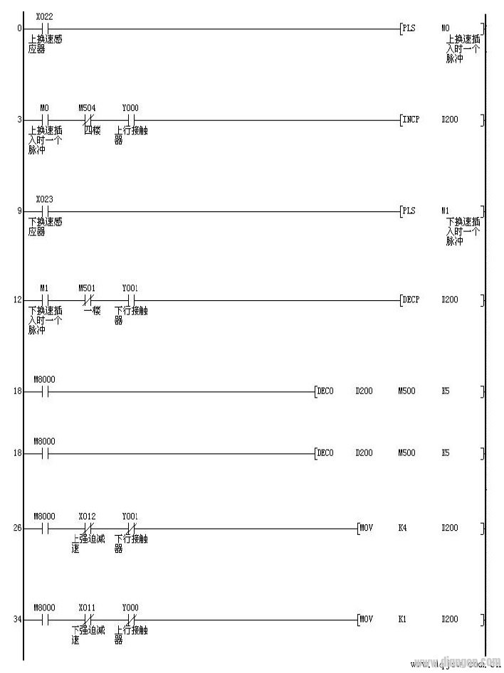
1. When the elevator is going up, whenever the upper speed sensor is inserted into the magnetic isolation plate, M0 has a cycle trigger.
2. M0 pulls in and makes the value in register D200 increase by 1.
3. When the elevator descends, each time the speed change sensor is inserted into the magnetic isolation plate, M1 has a cycle trigger.
4. M1 pulls in and reduces the value in register D200 by 1.
5. When the elevator descends to the lowest level and the forced switch is actuated, the value in D200 is forced to 1.
6. When the elevator goes up to the highest level and the forced switch is actuated, the value in D200 is forced to 4.
(here, 4 layers are taken as an example)
In this way, the actual value in the D200 reflects the actual floor value of the elevator. The D200 is decoded to obtain the first floor when the M501 is closed, the second floor when the M502 is closed, and the third floor when the M502 is closed. It is the 4th floor. At the same time, the elevator deceleration signal is also given when the elevator performs floor reversal.
About NOMEX Coated Copper Wire
Products Feature: Due to the electrical, chemical and mechanical integrity of NOMEX paper, and elasticity, flexibility, tear resistance, moisture resistance and wear resistance are very good, and very resistant to acid and alkali corrosion, good elasticity and aging, withstand thermal shock performance.
Application: mobile transformer, traction transformer, pole-mounted distribution transformer, power substations, rectifiers, furnace transformer oil-immersed transformer coil winding, welding machine.

Name
NOMEX Coated Copper Wire
Conductor
Copper
Dimension(mm)
Rectangular: Thickness(a): 0.90 ~ 5.60
Width(b): 3.15 ~ 16.0
Insulation Material Type
NOMEX Paper
(Single, double, triple multi-layers or
according to your requirement)
Standard
IEC; ISO9000; ISO9001; IATF16949
Packing
50kg~150kg ply-wood spool
Application
Transformer, welding machine,
electromagnet or other similar electrical equipment.
Copper Wire,Nomex Coated Copper Wire,Nomex Paper Covered Copper Wire,Copper Rectangular Wire
HENAN HUAYANG ELECTRICAL TECHNOLOGY GROUP CO.,LTD , https://www.huaonwire.com