High-quality wireless audio repeater designed by VMR6512
The wireless FM audio transponder can modulate the audio signal into a high-frequency signal and receive it with an FM radio within a certain distance. Wireless audio transponders are widely used in wireless headsets, car MP3 transponders, conference broadcasting, building and park broadcasting and other places. The simplest wireless audio repeater can be constructed with only one transistor, as shown in the following figure: 
Figure 1 Single tube audio FM transponder
The figure above uses a triode 9018 to form an oscillator. The audio signal is input from the base of the triode, and the frequency modulation is realized by using the variable capacitance diode characteristic of the BE junction. Although this circuit is simple, the sound quality is very poor, the stability of the oscillation circuit is very bad, the change of voltage, the appearance of the human body or metal objects near the antenna will change the oscillation frequency and cause the instability of the receiving end. And the circuit can only transmit mono audio, users cannot hear high-quality stereo music.
More complex stereo transponders use integrated circuits, the most commonly used is BA1404 of RoHM. The circuit set integrates a stereo encoder, which can generate a 19kHz stereo pilot signal to be transmitted with the audio. If the radio has a stereo decoding function, it can demodulate stereo music. The application circuit of BA1404 is shown below: 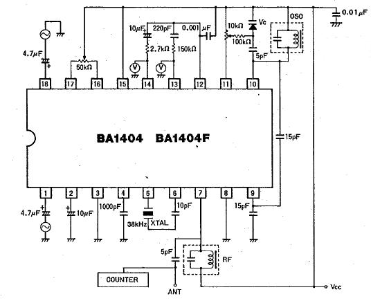
Figure 2 BA1404 application circuit
Compared with the single-tube transponder, BA1404 can not only transmit stereo signals, but also improve the sound quality, but the separation, frequency response and other indicators are still not very ideal. Because the LC oscillator is still used in the BA1404, the stability of the frequency is still not good enough, and the phenomenon of frequency drift is easy to occur. There are quite a few car audio transponders or wireless earphones with BA1404 on the market now.
To create a broadcast-grade sound quality and a very stable frequency FM wireless repeater, you need to use digital audio preprocessing and frequency synthesis and other complex technologies. Due to cost and complexity, these technologies are usually only used in radio stations, which is difficult for ordinary users to accept.
Is it that the high-stability, Hi-Fi audio quality audio repeater has no chance with ordinary users? The wireless audio forwarding module VMR6512 developed by Beijing Ruiyufei Technology Co., Ltd. has solved the contradiction between cost and sound quality and frequency stability, so that everyone can enjoy broadcast-level sound quality at a low cost.
The following figure is the internal block diagram of the VMR6512 wireless audio modulation module. 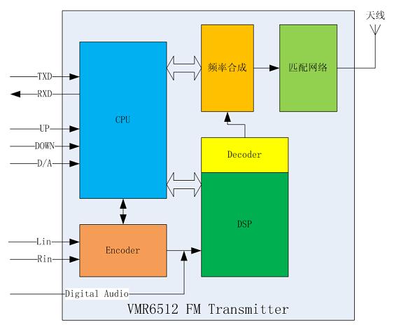
Figure 3 VMR6512 wireless audio repeater block diagram
The VMR6512 wireless audio forwarding module has the following characteristics:
ï¬ Broadcast-grade sound quality ï¬ Fully integrated package, which can work without any external components ï¬ The audio is processed by DSP, which provides a guarantee for high sound quality ï¬ Frequency synthesis technology is adopted, the oscillation frequency is highly stable ï¬ The output power is adjustable, up to 115dBuV ï¬ Frequency range 88.0MHz-108.0MHz, low-end can be expanded to 76.0MHz according to requirements ï¬ Can input analog audio or digital audio ï¬ Equipped with external UART interface, can be conveniently controlled by external CPU or PC ï¬ Provide frequency setting UP / DOWN input , Easy to use independentlyThe module can be applied to:
ï¬ Hi-Fi wireless headphones ï¬ Car MP3 audio transponder ï¬ Wireless microphone ï¬ Conference broadcasting system ï¬ Building music playback ï¬ Park music playback ï¬ Accessories of audio-visual entertainment equipment ï¬ Campus radio stations A CPU controls the entire module inside the VMR6512. The external processor can communicate with the module through the UART serial port to set the frequency, transmit power, and interface mode of the module. In addition, the module also provides two pins, UP and DOWN, for frequency adjustment without an external CPU or control serial port. The default power-on transmit frequency of the module is 100.0MHz. For each low-level pulse on the UP or DOWN pin, the transmit frequency increases or decreases by 0.1MHz. If the low level is continuously maintained on these two pins, the transmission frequency changes every 0.3 seconds.
The audio signal interface can be a common analog audio input or a digital audio input. Analog audio is first converted to digital signals by an audio A / D converter and then processed by the DSP. Digital audio provides three commonly used interface modes such as I2S, left-jusTIfied, and DSP, and can be seamlessly connected to almost any codec or DSP.
After the audio signal is digitized, the DSP performs a series of processing on the signal, such as filtering, pre-emphasis, and pilot generation. Because it is processed in the digital domain, it has the advantage that analog circuits cannot match, providing a prerequisite for high sound quality.
The module also integrates the automatic gain control (AGC) function. When the input audio exceeds a certain threshold, the AGC will automatically attenuate the audio signal to avoid distortion. When the audio signal is below a certain threshold, the AGC circuit will amplify the audio signal to a certain extent, thereby ensuring that the receiving end always has a suitable volume output.
The signal processed by the DSP undergoes D / A conversion and is sent to a high-frequency modulator for FM modulation. The high-frequency signal is generated by frequency synthesis. The frequency can be adjusted in steps of 10KHz. The frequency range is continuously adjustable from 88.0MHz-108MHz, and can be extended to 76.0-108.0MHz if there are special needs. The frequency deviation of the FM modulated signal can also be adjusted precisely, but it is generally not recommended to be set by the user. The maximum output FM signal power is 115dBuV, and the transmission distance in open areas can reach 50 to 60 meters.
The following figure is the appearance and pins of VMR6512: 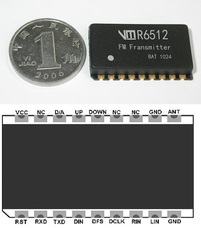
Figure 4 VMR6512 module outline and pin description
The overall size of the VMR6512 module is only 25mmx15mmx3.8mm (length x width x height), which can be easily embedded in small devices such as wireless headphones and car MP3 audio transponders.
The following figure is the component symbol and pin description of VMR6512: 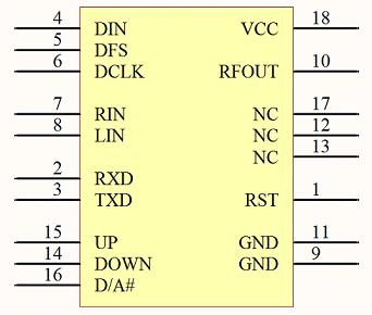
Figure 5 VMR6512 component symbol table 1 VMR6512 pin description
Pin No. | Name | DescripTIon |
1 | RST | Reset, high level resets the module |
2 | RXD | Control serial input RX |
3 | TXD | Control serial output TX |
4 | DIN | Digital audio data input |
5 | DFS | Digital audio frame sync signal input |
6 | DCLK | Digital audio clock signal input |
7 | RIN | Analog audio right input |
8 | LIN | Analog audio left input |
9 | GND | Ground |
10 | RFOUT | RF output |
11 | GND | Ground |
12 | NC | - |
13 | NC | - |
14 | DOWN | Frequency reduction input, the output frequency of each low-level pulse is reduced by 0.1MHz, and the continuous low level is repeated at a frequency of 0.3 seconds. |
15 | UP | Frequency increase input, the output frequency of each low-level pulse increases by 0.1MHz, and the continuous low level repeats at a frequency of 0.5 seconds |
16 | D / A | Audio input interface digital / analog selection |
17 | NC | - |
18 | VCC | Power input, 2.7-3.3V |
Table 2 Related parameters of VMR6512
symbol | Parameter Description | value |
Vcc | voltage | 2.7-3.6V |
Ic | Working current (maximum) | 32mA |
Fr | FM transmission frequency | 88.0-108.0MHz |
Fon | Power-on default frequency | 100.0MHz |
Pmax | Maximum RF power | 115dBuV |
Ss | Stereo separation | 35dB |
SCR | Offset frequency suppression | 50dB |
Afl | Filter-3dB low end | 25Hz |
Afh | Filter-3dB high-end | 16kHz |
Fm | Modulation frequency deviation | 68.25KHz |
Rf | Audio response flatness (30Hz-15KHz) | ± 1.5dB |
Rin | input resistance | 56kOhm |
Vain | Audio input amplitude | 350mVp-p |
The following figure is the reference design circuit diagram of VMR6512: 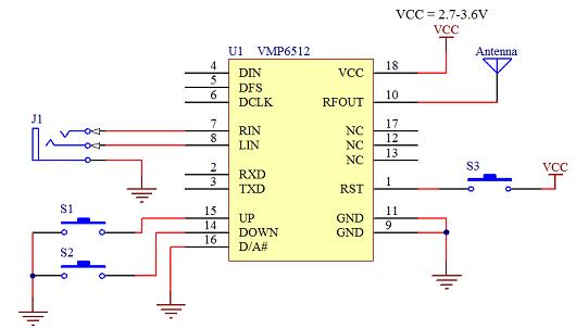
Figure 6 VMR6512 reference design circuit The reference design in the above figure is based on the VMR6512 independent working mode design. S1 and S2 are used to adjust the frequency increase and decrease respectively. S3 is used for Reset of the entire module. The antenna using 75cm length of wire will get better results.
Of course, you can also use a single-chip computer or PC to control the VMP6512, and connect the digital signal, which can further improve the flexibility of the transponder and obtain higher sound quality. How to control the VMR6512 through the serial port will not be repeated in this article.
Under normal circumstances, the transmission distance of the VMR6512 can reach more than 50 or 60 meters in an open area (depending on the sensitivity of the antenna and radio), which is enough to meet most needs. In some special applications, if you need to transmit a longer distance, you can use VMR6512 with another product of Beijing Ruiyufei Technology Co., Ltd.-VMR6700 high-frequency power amplifier to extend the transmission distance to more than 1.5 kilometers. Of course, this requires permission from the relevant department.
VM series modules are packaged with high temperature resistant materials, so reflow soldering can be used for soldering. It is also very convenient to solder with an electric iron in amateur conditions. Prepare a pointed soldering iron and some fine solder wire (best below 1mm). First apply some flux on the pad, and then put the module in the accurate position, so that the pins on the module correspond to the pad one by one. Put the solder wire into the half-hole notch, and gently touch the solder wire with a soldering iron, and soon the solder will melt and firmly weld the half-hole pad of the module to the pad of the bottom plate. The welding operation is shown below: 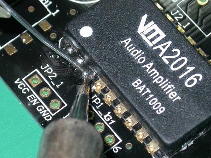
Figure 7 Manual welding of VM series modules
Our Led Fish Light is popular in led market, cause its elegant outlook and its high quality and competitive price.
Key Features
1.The lifespan is over 50000 hours,low maintenance costs.
2.Energy conservation,saving over 80% energy than the traditional HPS.
3.High light efficiency,90% of the light will be absorbed by the aquatic plants,while just 8%-10% to the HPS.
4.Build-in cooling system,could solve the heat dissipation excellently.
5.Built-in power supply, CE approved, No setup required, just simpler and safer plugs directly into AC85V-264V, no reflector & ballast needed.
Philizon enjoys a high reputation in grow led lamp and LED Fish Light fields throughout Europe and America, Philizon also insists on taking high technology to design the newest&best Led Grow Light and LED Fish Light constantly as the market request. Our R&D team with more than 10 people has rich experience in appearance design, electronic structure,heat dissipation simulation analysis, optical lens design, lightcontrol system etc. Most of our hydroponics full spectrum Led Grow Lighting and LED Fish Light are private modules,we have 10 more design patent and utility model patent till now.
Item Display


Convenient in using lights at the same time.

Package Include
1 X Free Hanging Kit
1X Free Power Cord


Quality Control systems and after-sales

All the lamps have passed strict quality examination and are packed carefully before shipping.In order that our customers get high quality lamps,we attach importance to every details.
Application
1. coral reef lighting,fish tank lighting,coral reef tank lighting
2. Aquarium Lighting ,aquarium art,aquarium shop,aquarim centre
3. fish bowl lighting,fish lighting,freshwater lighting,saltwater lighting

Our Company


Philizon Advantages
Professional: we are professional Led Grow Lights and Led Aquarium Light manufactuer here in China,you will get Professional and High quality LED Grow Lights and LED Fish Light from us and get good guarantee.
Cost-effective Price:we don`t have the lowest price,but the LED Fish Light you get from us really cost-effective,good quality & decent price.
Win-win situation:Long term business is our mission,we will provide good LED Fish Light and warming service to build a long-term business relationship with you
24/7 unlimted customer service: we are always here for you for your question,any question just email us or call us,we do our best to help you all the way.
Long term warranty: Don`t worry about the quality and we guarantee you 3years warranty for all the Led Plant Grow Light and Coral Reef Led Aquarium Light.
Best buying experience: you will get the tiptop serive you have ever had,just have a try and you`ll see.
Trade Terms
Payment: T/T, L/C, Paypal, 30% deposits before production, 70% balance to be paid before deliverying(Western Union are welcome)
Sample will be delivered within 7 working days.
Discounts are offered based on order quanlityes.
MOQ:sample order are acceptable
Delivery ways:DHL,UPS,FedEx,TNT, door to door,by sea,by air,etc.
Our products ranges:
LED Plant Grow Lights for agricultural lighting;
LED aquarium lights for fish tanks,corals,saltwater tank,marine tank with reef,coral,sps,lps,fish,etc;
Warmly welcome to take a visit on our factory at any time and we will pick you up at the airport in Shenzhen.
LED Fish Light
Led Fish Light,Led Fish Tank Lights,Aquarium Lighting,Fish Tank Lights
Shenzhen Phlizon Technology Co.,Ltd. , https://www.philizon.com