Basic principle of video decoder in monitoring and inspection system
Video inspection systems have been widely used in commercial and industrial fields. Cameras-from cheap and low-resolution products in black-and-white closed-circuit television (CCTV) systems to advanced and high-resolution products in digital video systems-are used for everything from product inspection, traffic supervision to real-time face recognition Application occasions.
The video itself carries a lot of data, which makes the signal processing and data storage tasks quite complicated. By discarding useless information and passing only important parts of the picture, the video inspection system can be simplified, saving memory and computing cycles. Figure 1 shows the components of a typical system.
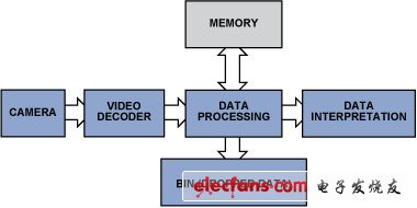
Figure 1: Simplified video inspection data flow.
This article will explain how to extract useful data to minimize processing requirements, memory capacity, and DSP utilization, and introduce how the special features of ADI ’s video decoder can simplify video algorithms and speed up the development of video inspection systems.
Example 1: Count and inspect objects
Imagine that a wide conveyor belt is quickly transferring many products, and the large number of products makes manual counting very difficult. In addition to automating counting tasks, cameras can also be used to monitor product quality. This can be achieved by modifying the simple counting algorithm to focus it on specific details and flaws.
Storing all video data requires a lot of memory, and processing a lot of data also requires a lot of hardware resources and processing power. Therefore, when inspecting the products on the conveyor belt, the system will not collect the entire picture data into the memory, but will find the details of interest from the large amount of data and discard as much useless data as possible.
In most cases, grayscale pictures carry enough information, so RGB signals can be converted to (luminance only) Y signals, and chrominance information is discarded. Then use the edge detection method to check the content in the monochrome picture to find the products on the conveyor belt, and then compare their shapes with the template to determine whether the product is normal.
The edge detection algorithm-only requires a few lines of active video and a small amount of memory-can find the discontinuity of the brightness of adjacent pixels by calculating the first and second derivatives of the active picture, see "Digital Image" by Bernd Jähne Processing ". In practical applications, edge detection can be achieved by extracting information using matrix calculation methods, such as the Sobel matrix operator. In FPGA (Field Programmable Gate Array) implementation, such edge detection in pixels can provide satisfactory results. The article "A proposed FPGA Based Architecture for Sobel Edge DetecTIon Operator" written by Tanvir A. Abbasi and Mohm Usaid Abbasi introduces a simple FPGA implementation scheme. The noise can also be eliminated by adding a Gaussian two-dimensional filter. For details, see "Hardware AcceleraTIon of Edge DetecTIon Algorithm on FPGAs" by Mathukumar Venkatesan and Daggu Venkateshwar Rao. This article introduces a successful implementation of a detector similar to the Canny edge detector.
There are several other optimization algorithms that can be used to improve picture quality, but these algorithms all occupy valuable resources in FPGA design. However, some integrated circuit (IC) video decoders have integrated practical preprocessing algorithms or filters, so choosing such an IC can save FPGA resources. For example, the ADV7802 video decoder includes the Transient Luminance Improvement (LTI) and Chroma Transient Improvement (CTI) modules. These modules improve picture quality by improving the sharpness of brightness and chromaticity changes, and use adaptive peaking and non-linear methods-without adding noise or introducing defects-very useful in the edge detection process. In addition, brightness shaping and other built-in input filters can eliminate high-frequency noise from the signal source-focus on the signal and ignore the accidental noise.
![]()
Figure 2: LTI / CTI operation diagram.
Edge detection provides information about the changes in the edge of an object, not the entire picture of the object. The amount of data can be reduced from 3 × 8 bits / pixel (bpp) to 1bpp, thus saving a lot of memory space:
640 pixels × 480 pixels = 307, 200 bits (at 1bpp)
800 pixels × 600 pixels = 480,000 bits (at 1bpp)
1024 pixels × 768 pixels = 786,432 bits (at 1bpp)
1280 pixels × 720 pixels = 921,600 bits (at 1bpp)
By converting RGB to Y, storing only a few lines of active video in memory, and using FPGA algorithms, we can detect objects and observe their shapes. Once we know the position of these objects on the moving conveyor belt, we can estimate their movement and collect color or other information from the next frame to ensure that the minimum memory space is used. This process involves:
Edge detection
Store information
Predict the next position xn + 1
Extract information from preset product location areas
The LED Indicator is a device that monitors the operation or position of an electrical device with light. The indicator light is usually used to reflect the working state of the circuit (with or without electricity), the operating state (running, outage or test) of the electrical equipment, and the position status (closed or disconnected).
In our company,mainly have eight series(as follow):
AD22-22DS LED Indicator
AD22-4SMD LED IndicatorAD16 LED Indicator
AD22-22MSD Buzzer
AD22-30DS LED Indicator
AD22-DAV Current Voltage Indicator
AD22-DAM Current Indicator
AD22-DVM Voltage Indicator
LED Indicators,LED Indicator Light,LED Indicator Lamp,LED Indicator Bulbs
Ningbo Bond Industrial Electric Co., Ltd. , https://www.bondelectro.com