ASON routing technology architecture
This article mainly discusses the routing technology in Automatic Switched Optical Network (ASON). First introduced the ITU-T ASON routing technology architecture and technical requirements for ASON routing. Then discusses the differences between ASON routing technology and IP network routing. Then it analyzes the extension of IETF GMPLS to IP routing protocols, including OSPF-TE and IS-IS-TE. Finally, the progress of OIF in the NNI routing protocol is introduced.
Keywords: ASON, GMPLS, NNI, routing
1. Preface The emergence of automatic switched optical network (ASON) is a historic breakthrough in the development of transport networks. ASON, also known as intelligent optical network, is a network that uses an independent control plane to implement dynamic configuration connection management. The core technologies of the ASON architecture include signaling protocols, routing protocols, and link resource management. Among them, the signaling protocol is used for the management of the establishment, maintenance and removal of distributed connections; the routing protocol provides the routing service for the establishment of the connection; the link resource management is used for the link management, including the verification and maintenance of the control channel and the transmission link .
This article mainly discusses ASON routing technology, first introduces ASON routing technology architecture, including ASON routing technical requirements and routing information distribution topology. Then discusses the differences between ASON routing technology and IP network routing. Next, I introduced the extension of IETF GMPLS to the IP routing protocol. Finally, the progress of OIF in the NNI routing protocol is introduced.
2. ASON routing architecture ITU-T G.7715 defines the structure and requirements for establishing SC and SPC connection routing functions in an ASON network. The main content includes ASON routing structure, path selection, routing attributes, abstract information and state diagram transfer and other functional units. The purpose of G.7715 is to provide a protocol-independent method to describe the routing technology used for ASON. Routing messages are transmitted through a data communication network (DCN), and G.7712 specifies a possible implementation of DCN. In order to provide routing services, it is necessary to understand the situation of network resources in advance. These resources can be configured manually or discovered automatically.
The ASON routing architecture supports different routing methods defined by G.8080, such as hierarchical routing, hop-by-hop routing and source routing. This structure also abstracts the different expressions of routing information, such as link status and distance vector. The ASON routing architecture is used after the network is divided into multiple routing domains and the network resources are allocated.
(1) Basic concept Operators can divide the network based on a specific strategy. The basis of the division can be geography, management scope, technology, etc. Operators can regard the subdivided network as composed of different routing domains in order to provide routing services. The routing domain provides abstraction of routing information, thereby making the representation of routing information extensible. The routing domain is provided by the routing executor (RP) to provide services (such as channel calculation), the routing executor is a confederation of routing controllers (RC), and each RP is responsible for controlling a routing domain. RP supports the channel calculation function in its routing domain that provides routing services, and is consistent with the routing paradigm defined by G.8080 (source routing, hierarchical routing, and hop-by-hop routing). The channel calculation function supported by RP is based on the type of information provided by the routing information database.
Routing domains can be included hierarchically. In the routing hierarchy, each routing domain is associated with an independent RP. Each level in the routing hierarchy can use RPs that support different routing modes. The implementation of RP can be based on a distributed routing controller. The RC provides a routing service interface, which is the service access point defined for the RP. The RC is also responsible for the coordination and distribution of routing information. The RC service interface provides routing services at a given level of NNI reference point. Different RC instances may be restricted by different strategies due to the different organizations that provide services. The implementation of the strategy can be through different mechanisms, such as the use of different protocols.
The implementation of RC can be a set of distributed entities, which is called a routing control domain (RCD). RCD is an abstract entity that hides the internal details of the routing control domain and provides an interface with the same characteristics as the RC distribution interface. The routing information attributes exchanged between RCDs contain the common semantics of the routing information exchanged between RC distribution interfaces and allow different expressions to be used in each domain. The implementation of RCD depends on the specific implementation.
The relationship between RA, RP, RC, and RCD is given in Figure 1. 
Figure 1 The relationship between RA, RP, RC, and RCD is shown in Figure 1. The routing domain contains routing domains, which define successive hierarchical routing levels recursively. An independent RP is associated with a routing domain. By analogy, RP itself is realized by distributed RC, RC1 comes from RPRA, RC2 comes from RPRA.1 and RPRA.2. It can be found that the characteristics of the RCD distribution interface and the RC distribution interface are consistent.
(2) Routing architecture and functional components The routing architecture includes protocol-independent components such as Link Resource Manager (LRM) and RC, as well as protocol-related components such as Protocol Controller (PC). RC handles abstract information used for routing. The PC processes the protocol-related messages according to the reference points (such as E-NNI, I-NNI) through which the information passes, and passes the routing primitives to the RC. Figure 2 shows an example of routing features. 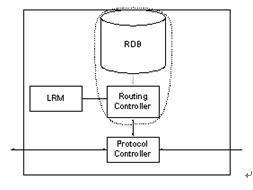
Figure 2 Examples of routing functional components  Routing controller (RC): RC functions include exchanging routing information with the peer RC, and replying to routing queries (path selection) through operations on routing information packets. RC has nothing to do with the agreement.
 Routing Information Database (RDB): RDB stores local topology, network topology, reachability and other information obtained through the exchange of routing information, as well as configuration information. RDB can contain routing information for multiple routing domains. RC can be connected to a view of RDB (specific term for relational database. A view is a virtual table, which has no storage space itself, but is derived from a table actually stored in the database. The usage of the view is the same as the physical table, and Make different users see different formats of the same data, and use authorization mode to control users' access to sensitive data). The dotted box in Figure 2 shows this relationship. RDB is protocol independent. Since the RDB can contain routing information of multiple routing domains (that is, it may be a multi-layer network), the RC connected to the RDB may share routing information. As shown in Figure 3.
 Link Resource Manager (LRM): LRM provides the RC with all SNPP link information and informs the RC of any state changes in the link resources it controls.
 Protocol Controller (PC): The PC converts the routing primitives into protocol messages of a specific routing protocol, so it is related to the protocol. The PC also processes protocol-related control information used for routing information exchange. 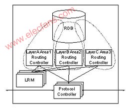
Figure 3 Relationship between RDB and multiple RC / routing domains
(3) Hierarchical routing domain Figure 4 shows an example of the routing domain. The high-level routing domain (parent) RA includes the low-level routing domain (child) RA.1, RA.2 and RA.3. Similarly, RA.1 and RA.2 further include routing domains RA.1.x and RA.2.x. 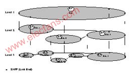
Figure 4 Example of routing domain classification
3. The difference between ASON routing and IP network routing In IP networks, data forwarding is carried out hop by hop, without the need to establish a connection in advance. In an optical network based on circuit switching, data exchange is based on end-to-end, and a connection needs to be established in advance. In addition, in an IP network, each router performs independent routing based on the destination address in the IP packet. Therefore, in order to prevent incorrect routing or routing loops, each node must use the same network topology database and routing algorithm. In contrast, in optical networks, routing is given when a connection is requested, and existing services are not affected when a connection establishment request is transmitted.
Since the routing protocol in the optical network does not directly participate in the exchange of the data plane, it can be considered that it does not affect services. For example, inaccuracies in topology and resource status may affect the establishment of new connections (or restore connections), but will not tear down existing connections. This makes the routing protocol of the optical network very flexible to include all kinds of new information. In fact, any information that helps route calculation or service differentiation can be included in the routing protocol. The information can be standard or vendor-specific. Because the connections in the optical network are explicit routes, and for a specific connection, the routing calculation is completed by a single network element, so different network elements do not need to use the same routing algorithm. In fact, for the same information, different routing algorithms can adopt different processing methods.
Bandwidth statistics in optical networks are also simpler than IP networks, making bandwidth resource management easier. This will affect how protection and recovery bandwidth is allocated. In an IP network, a protection channel can be configured in advance without occupying network resources before a failure occurs. In a circuit-switched network, establishing a protection channel usually requires corresponding resources. This basic difference restricts the direct application of some traffic engineering mechanisms in IP networks to optical networks.
The neighbor discovery process is a basic function of IP routing protocols in many domains. Neighbor discovery in optical networks is implemented by other automatic discovery mechanisms. In optical networks, this process includes the discovery of link-related attributes in addition to basic neighbor discovery. Although most control plane information can be transmitted in-band or out-of-band, some automatically discovered information must be transmitted in-band. ITU-T G.7714 defines the basic model of the auto-discovery process, and IETF ’s LMP protocol defines a common implementation.
4. GMPLS extension to routing protocols
MPLS extends the traditional routing protocols (ISIS-TE and OSPF-TE) to support traffic engineering. GMPLS has extended and strengthened it on this basis to support the transmission of link state information. The extension of GMPLS to routing protocols mainly includes support for unnumbered links, as well as support for link protection types (LPT), shared risk link group information (SRLG), interface exchange capability descriptors, and bandwidth coding. GMPLS-OSPF and GMPLS-ISIS describe the specific implementation of extended functions by OSPF-TE and ISIS-TE, respectively. GMPLS routing protocol is mainly used for routing of I-NNI interface.
(1) Support for unnumbered links
All links in an MPLS network usually have IP addresses. When a path is calculated in the network, the links that make up the path are identified by their IP addresses. The information is transferred to the signaling protocol, and then the signaling protocol establishes the path. Therefore, it seems that every link must have an IP address. But it is worth considering to assign IP addresses to each fiber, wavelength, and TDM channel. One factor is the lack of IP addresses, and the other factor is the difficulty of management. Unnumbered links can be used to solve this problem.
An unnumbered link must be a point-to-point link. The LSRs at both ends of the link assign an identifier to the link. This identifier is a non-zero 32-bit number and is unique within the scope of the LSR assigned to the identifier.
Support for unnumbered links includes transmission link identifier information. When an LSR broadcasts an unnumbered TE link, the broadcast includes the local and remote identifiers of the link. If the LSR does not know the remote identifier of the link, 0 is used as the remote identifier.
(2) Link protection type Link protection type (LPT) indicates the protection capability of the link. Using this information, the path calculation algorithm can establish an LSP with appropriate protection characteristics. LPT is organized by level, and the least acceptable protection method is specified when establishing the channel, and then the path selection algorithm is used to find the path that can meet the conditions. The protection schemes are arranged from low to high.
 Extra traffic: If the protection type of the link is extra traffic, it means that the link is used to protect other links. If any link protected by the link fails, the LSP carried by the link will be lost.
 Unprotected: If the protection type of the link is unprotected, it means that no other link protects the link. If the link fails, the LSP it carries will be lost.
 Shared (Shared): If the protection type of the link is shared, it means that there are one or more disjoint extra service links to protect the link. These additional service-type links are shared by one or more links.
 Dedicated 1: 1 (Dedicated 1: 1): If the protection type of the link is dedicated 1: 1, it means that there is a dedicated and disjoint extra service link to protect the link.
 Dedicated 1 + 1: If the protection type of the link is dedicated 1 + 1, it means that there is a dedicated and disjoint link to protect the link. However, the link state database does not broadcast the link used for protection, so the link cannot be used for LSP routing.
 Enhanced (Enhanced): If the protection type of the link is enhanced, it means that the link uses a more reliable protection scheme than the dedicated 1 + 1, such as 4-fiber MS-SPRING.
The link protection type is optional. If the link state broadcast does not carry this information, the LPT is unknown.
(3) Shared risk link group information If a group of links share a certain resource, and the failure of this resource may affect all these links, this group of links is called a "shared risk link group" (SRLG: Shared Risk Link Group). For example, two fibers in the same pipe belong to the same SRLG. A link can belong to multiple SRLG. Therefore, the SRLG information is a list of all SRLGs to which the link belongs. A SRLG is identified by a 32-bit number, which is unique within an IGP domain. The SRLG information is an unordered list of all SRLGs to which the link belongs.
The SRLG of an LSP is a combination of the SRLGs of all links constituting the LSP. A bundled SRLG is a combination of all member links SRLG. If it is required to establish multiple LSPs with different routes between two LSRs, the calculated path should not contain the same link, that is, the SRLGs of the paths are disjoint.
The SRLG information can be set to an initial value and does not change over time (unless it is reconfigured). The SRLG information is optional. If the LSA does not contain SRLG information, the SRLG of the link is unknown.
(4) Interface exchange capability descriptor
GMPLS interfaces can have different switching capabilities. The interfaces at both ends of a link can also have different switching capabilities, and the interfaces of the same node can also have different switching capabilities. The interface exchange capability descriptor describes the exchange capability of the interface. For a bidirectional link, the two directions of an interface have the same switching capability.
The LSA of the link only carries the near-end interface exchange capability descriptor. LSR uses the link state database (LSD) to determine whether a link is unidirectional or bidirectional. For bidirectional links, LSR uses LSD to determine the remote interface exchange capability descriptor. For unidirectional links, it is considered that both ends of the link have the same interface exchange capability descriptor.
GMPLS defines the following interface switching capabilities:
PSC: packet switching L2SC: L2 switching TDM: time division switching LSC: wavelength switching
FSC: Fiber switching can use a two-dimensional array containing interface switching capabilities to describe a TE link. Here are some examples:
[PSC, PSC]: a link between two data LSRs
[TDM, TDM]: a link between two DXCs
[PSC, LSC]: a link between LSR and OXC
[TDM, LSC]: A link between DXC and OXC (5) Bandwidth coding
GMPLS uses the IEEE floating-point format to represent discrete bandwidth values, including remaining bandwidth, maximum / minimum LSP bandwidth, etc.
5. NNI routing protocol Currently, OIF is working on the formulation of inter-domain routing protocol. OIF accepted the technical requirements of ITU-T G.7715 on ASTN routing, as well as the definition of structure and terminology, and used it as the basis for formulating NNI routing. G.7715 defines the concept of routing hierarchy, and within a certain layer, the network can be divided into multiple routing domains, and each routing domain can contain smaller routing domains. This gave rise to the concept of routing hierarchy. OIF NNI requires that routing protocols support at least 4 routing levels, and that different routing domains at the same routing level can run different routing protocols. The path calculation is only performed at a certain level, which can be hierarchical routing, hop-by-hop routing and source routing. OIF also requires that E-NNI and I-NNI routing protocols are independent of each other. The routing protocol of GMPLS cannot meet the requirements of G.7715 because the domain defined by OSPF or IS-IS is different from the domain defined by G.7715.
According to ITU-T G.8080 and G.7715, the reference model of OIF E-NNI is shown in Figure 5. In this reference model, routing protocols need to be run at three levels, namely E-NNI between operators, E-NNI and I-NNI within operators. EBGP is the main candidate routing protocol for E-NNI among operators. I-NNI can use any proprietary routing protocol, so no standardization is required. Therefore, the main job of OIF is to formulate E-NNI routing protocols within operators. 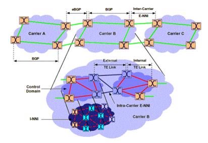
Figure 5 OIF E-NNI reference model
The NNI candidate routing protocols that OIF is considering include DDRP, BGP, and GMPLS OSPF-TE, and DDRP is based on OSPF and IS-IS. DDRP (Domain to Domain RouTIng Protocol) is a hierarchical link state routing protocol that meets the routing architecture of G.7715. DDRP is not a new routing protocol, but based on OSPF and IS-IS. DDRP can be used in the NNI routing protocol to achieve interoperability between different manufacturers. Table 1 gives a comparison of these protocols.
Table 1 Comparison of NNI routing protocols

6. Conclusion
ASON routing technology is one of the core technologies of the entire automatic switching optical network, and is still under further research. ITU-T's G.7715 defines an ASON routing architecture that has nothing to do with the protocol. The next step is to formulate specific routing protocol implementation specifications. IETF mainly extends the existing intra-domain routing protocols to support the needs of transport network routing. OIF focuses on the formulation of routing protocols for E-NNI interfaces. In order to formulate a perfect ASON routing technology architecture, we need to consider the research results of these standardization organizations.
references:
1. Yong Xue, et al. "Architecture and Requirements for RouTIng in the AutomaTIcally Switched OpTIcal Network", ITU-T G.7715 v0.6.4, May, 2002.
2. K. Kompella, et al. â€Routing Extensions in Support of Generalized MPLS†draft-ietf-ccamp-gmpls-routing-04.txt (work in progress).
3. OIF2002.087.4, "NNI Routing using OSPF-TE", OIF, July 22, 2002.
Wide range of Enclosures collections options for possible battery pack application as well as other application.
Please search ECLAAAxBBB for the target size options. For example, ECL200x100 for 200mm(200~209mm) length, 100mm(100~109mm) width solution.
Enclosures
Plastic Enclosure,Junction Box,Connect Box,Electrical Box
Asarke Industry Co., Limited , https://www.asarke-industry.com