Eight key points describe the rules to follow when drawing an electrical schematic
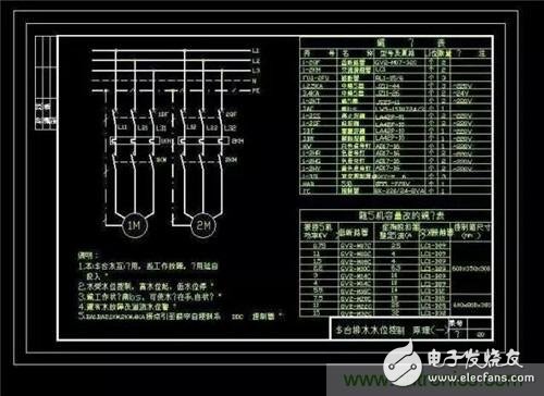
1. In order to distinguish the main circuit and the control circuit, the main circuit (motor, electric appliance and connecting line, etc.) is indicated by thick lines when drawing the circuit diagram, and the control circuit (electrical appliances and connecting lines, etc.) is indicated by thin lines. It is customary to place the main circuit on the left (or upper) of the wiring diagram and the control circuit on the right (or lower).
2. The power circuit, control circuit and signal circuit should be drawn separately:
Power circuit - the power circuit draws the horizontal line; the powered power equipment (such as the motor) and other protective electrical circuit branches should be drawn in the vertical power circuit.
Control circuit and signal circuit - should be drawn vertically between two horizontal power lines, energy-consuming components (such as coils, electromagnets, signal lights, etc.) should be directly connected to the grounding or under the horizontal power line, control contact connection Between the upper horizontal line and the energy consuming element.
3. In the schematic diagram, each appliance is not drawn on the line according to its actual layout. Instead, the components of the same appliance are painted separately where they are completed.
4. In order to distinguish the type and function of each electrical appliance in the control line, each electrical appliance and its components are represented by certain graphical symbols, and each electrical appliance has a text symbol that belongs to each component of the same electrical appliance (such as a contactor). Both the coil and the contact) are indicated by the same text symbol. The same electrical appliances are represented by a certain numerical serial number.
5. Because each appliance performs different actions in different working phases, the contacts are closed when they are closed, and only one situation can be indicated in the schematic diagram. Therefore, the contacts of all electrical appliances are specified to indicate normal positions, that is, The position of the appliance when the coil is not energized or the machine is not yet operating. For example, for the contactor and the electromagnetic relay, the position where the electromagnet is not sucked is the position where the contact switch, the button, etc. are not pressed.
6, in order to check the line is convenient. In the schematic diagram, the electrical connection of two or more wires should be marked with a dot, and each contact should be marked with a number. The principle of numbering is: the singular number is marked near the left power line, and the double number is marked near the right power line. Usually, the coil or resistor of the electric appliance is used as the boundary line between single and double numbers, so the coil or resistor of the electric appliance should be placed on the side (left or right) of each line as much as possible.
7. For the mechanism with circular motion, the work cycle diagram should be given. The universal transfer switch and the travel switch should draw the action program and action position.
8. The schematic diagram should indicate the following data or instructions:
1 The voltage value, polarity or frequency and phase number of each power supply circuit.
2 characteristics of certain components (such as resistors, capacitor parameter values, etc.);
3 Operating methods and functions of non-common appliances (such as position sensors, manual contacts, solenoid valves or pneumatic valves, timers, etc.).
ONEREEL cable drum rollers are an ideal labour and effort saving device for installating cables durining electrical installations. Making light work of handling and decoiling cables from cable drums.
cable drum roller,cable drum dispenser,cable drum holder,cable drum de-reeler
NINGBO BEILUN TIAOYUE MACHINE CO., LTD. , https://www.spool-manufacturer.com