Three ways to access 3G base stations
The metropolitan area transport network is the basis of the telecommunication network, and provides a transmission channel and a transmission platform for various services carried. With the development of the services carried by the transport network to the direction of IP, broadband and full-service, the service demand drives the development of the network to All IP, and the PTN bearer network becomes the mainstream IP bearer technology of the next-generation transport network. Other mainstream operators have begun to deploy PTN bearer networks on a large scale. As a traditional 2G bearer network, MSTP has formed a certain scale. The new packet transmission network and the original network will coexist for a long time, the 3G service will be carried out on the new network, and the 2G service will gradually migrate to the new network. There is also some business interaction between the two networks.
Three ways of 3G base station access PTN and 3G base station docking selectionCurrently, mainstream IP base stations can provide interfaces such as FE optical ports and FE electrical interfaces. The way in which the PTN access devices on the transmission side are connected to each other has become a topic of concern to operators around the world.
Safety—Electrical port is used, the cable is easy to loose, and the signal is easily lost. In contrast, the optical port is more secure.
Cost—The FE port on the transmission side is similar to the cost of the FE port. The optical port is required for the optical port. The base station side is equipped with an FE electrical port as standard. The FE optical port can be realized by adding an optical module. Compared with the cost of the optical port, the difference between the optical port and the electrical port is that the optical module has a lower cost.
Application—Connected with FE electrical port. Due to the limited transmission distance of the Ethernet cable, the maximum distance is less than 100 meters, which is only used for intra-office docking. The FE optical port is used for docking. The ordinary optical module has a transmission distance of 2.5km and a long-distance optical module of 15km. It can be used for docking in the same office or for inter-office docking.
Ring network accessThe installation conditions of the equipment room environment and power supply of the base station are good, and the installation requirements of the transmission equipment can be met. At the same time, the base station is a ring node on the optical cable route, and one PTN access device is placed in each base station, and each station forms a PTN GE. Access ring.
There are two principles for equipment selection. In the service-intensive area, a slightly larger capacity PTN access device can be connected to access more GE branches. In the future, devices can be upgraded to 10GE. Small-capacity PTN access devices can be placed in the sparsely populated area to control costs and save room space.
Branched network accessFor the equipment room where the base station is located, there is no DC power supply guarantee, and the base station with the transmission installation location is connected in the form of a branch; in addition, if the base station is end-chained on the optical cable route, the group network should be connected in a branched form. The device uses a small PTN access device (1U~2U).
Some of the sub-base stations already have SDH equipment in the base station, and only this one installation location. You can use the hard cutover mode to remove the SDH device and then install the PTN device. This mode will result in a long service interruption (5 to 10 minutes) and is applicable to non-critical business areas. This operation can be performed simultaneously with the operation of replacing the FE optical module on the base station side, and both construction personnel simultaneously enter the station to minimize the service interruption time.
Fiber is pulled far to the nearby macro stationFor the base station where the base station is located, there is no DC power supply guarantee, and the base station without transmission installation location is mostly based on the substation. This type of base station can directly pull the FE optical fiber from the BBU to the PTN equipment in the nearby macro station. The distance is 2 to 3 km and the farthest is no more than 15 km.
The advantage of this access method is that the construction difficulty is low and there is no need to consider the installation of the transmission equipment. And the transmission side saves the cost of the PTN end access device at one end. The disadvantage is that the end station lacks transmission equipment monitoring, and there is a fault in the remote section that cannot be quickly located. From the perspective of maintenance, the interface between the wireless professional and the transmission professional needs to be delineated, mainly in the cable of the remote section.
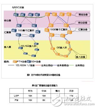
PTN bearer scheme for 2G base stationsAt present, some GSM new base stations only have PTN access devices installed on the access end, which need to be accessed by the PTN network, and then transferred to the SDH network, and interfaced with the BSC by using the E1/155M interface at the central office. The service protection mode is to enable the PW 1+1 protection on the PTN device. The SDH device is enabled with the TU12 SNCP protection. The STM-N interface card of the PTN has the PW and TU12 alarm conversion functions, so that the end-to-end protection of the E1 service can be guaranteed. There are two docking schemes, one is to transfer to the SDH landing device at the PTN core node, and the other is to switch to the SDH aggregation device at the PTN aggregation node.
In the solution shown in Figure 1, the bandwidth of the PTN core aggregation layer: 1 E1 service through the circuit simulation needs to occupy the 2.42M bandwidth of the PTN network, and cannot converge, which will consume a large amount of PTN core/aggregation layer bandwidth.
PTN network transmission efficiency: PTN is the development of transport packet services. Excessive E1 emulation services will greatly reduce the transmission efficiency of PTN networks.
Floor equipment pressure: The first generation of PTN equipment is not powerful enough to handle LSP/PW capability. It is the current network bottleneck, and all services at the core layer will increase the pressure on the core layer equipment (especially the E1 simulation service, each E1 must occupy 1 PW channel). The processing capacity of each manufacturer's landing equipment is shown in Table 1.
The second solution, the bandwidth of the PTN core aggregation layer: The transmission of the E1 emulation service to the SDH network as early as possible will save the bandwidth of the PTN core aggregation layer and occupy the bandwidth of the SDH core aggregation layer, which is in line with the actual situation of the network.
PTN network transmission efficiency: Transmitting the E1 emulation service to the SDH network as early as possible will improve the transmission efficiency of the PTN core aggregation layer.
Landing equipment pressure: Delivering the E1 simulation service to the SDH network as early as possible will disperse the pressure of the PTN landing equipment and improve the network performance. After comparison analysis, it can be seen that when the service is opened, the general situation should be preferred. The second node transfers the service to the SDH at the aggregation node. The internet.
As a connection-oriented transport technology, PTN draws on the perfect protection switching, rich OAM, good synchronization performance and powerful network management in SDH technology. At the same time, as a new technology, the construction of PTN network requires long-term verification of the existing network, accumulate various experiences, and continuously develop, and eventually become a reliable bearer network for rapidly developing IP services.
Energy Storage Battery,Battery Energy,Battery Energy Storage System,Storage Battery
Power X (Qingdao) Energy Technology Co., Ltd. , https://www.solarpowerxx.com