Battery charger control circuit diagram
The conventional battery charger typically employs a transformer for voltage conversion and charging. While this method offers certain benefits, such as automatic termination of charging, it also presents several drawbacks. Transformers tend to be bulky, prone to overheating, and may lead to inefficiencies in power conversion. However, this particular charger addresses these issues by incorporating thyristors and integrated circuits into its design. The accompanying schematic illustrates the circuit configuration.
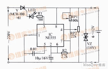
Battery Charger Control Circuit
The operational principle of the circuit is straightforward. Once the battery to be charged is connected, the integrated circuit (IC) is powered up. A pulse current is generated at the third pin of the IC, which triggers the unidirectional thyristor into operation. The variable resistor RP1 allows adjustment of the pulse current's frequency, thereby controlling the conduction angle of the thyristor and regulating the charging current. Additionally, RP2 serves a critical function, triggering the IC's fourth pin when the battery reaches full charge. This action halts the output of pulse current from the third pin, effectively stopping the charging process.
In terms of component selection, RP1 and RP2 are potentiometers for fine-tuning, while R1 and R2 are carbon film resistors. C1 is a ceramic capacitor, and C2 is an electrolytic capacitor. The IC used is the NE555, and the unidirectional thyristor should be chosen based on specifications such as a minimum voltage rating of 40V and a current capacity of at least 0.5A, with examples including MRC-100-6. The Zener diode VZ operates at 14V. Following assembly, adjustments are made using RP1 to set the desired charging current, followed by tweaking RP2 to ensure the battery charges fully before automatically ceasing.
This device is compatible with batteries ranging from 6V to 14V. However, it is unsuitable for charging high-resistance batteries, as it operates directly from the mains supply during charging. Therefore, caution must be exercised, and direct contact with any components should be avoided to prevent electric shock.
48V 100AH Powerwall Solar Battery
10kwh lifepo4 battery,48v 100ah lifepo4 battery,48v 200ah lithium ion battery,51.2v lifepo4 lithium battery
Shenzhen Jiesai Electric Co.,Ltd , https://www.gootuenergy.com