Implementation of Flash programming on JTAG interface
In order to solve the problem of saving the program code of TMS320VC55X series DSP system, a method of using the JTAG interface to burn Flash online and implement bootstrapping is designed. This online programming method uses the parallel external memory load (EMIF) interface to connect the TMS320VC5509 to the Flash chip, and the initialized segment of the application is programmed into the external extended flash memory according to the C55X series DSP boot table format by the shift program. Thereby achieving bootstrap startup. This method brings convenience to the software maintenance and upgrade of the DSP system and has practical application value.
introduction
Flash is a kind of memory that can be erased online without loss of information after power-off. It has the characteristics of low power consumption, large capacity, fast erasing speed and so on. How to program the program into Flash and load it into the RAM inside the DSP at power-on is the two basic problems of Flash in DSP system applications. This article is based on TI's TMS320VC5509A and AMD's AM29LV800 development system, which elaborates on the method of burning Flash online and implementing bootstrap startup.
1 hardware circuit design
Figure 1 shows the connection between the TMS320VC5509A and the AM29LV800. The Flash extension is in the CE1 space and the starting address is 200000. Since the TMS320VC5509A has only 14 address lines A0~A13, and the address encoding of Flash as the data storage space uses word addressing, the A0 signal of the DSP is invalid, so the lower 13-bit address lines A0 ~ A12 of the AM29LV800 chip are connected to the TMS320VC5509A. The address lines A1 ~ A13, the upper 6-bit address lines A13 ~ A18 are expanded by the buffer serial port.
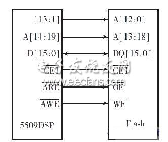
Figure 1 Connection diagram of TMS320VC5509A and AM29LV800
The AM29LV800 is a low-power flash that operates from 2.7 V to 3.6 V. The general stored data can be stored for more than 100 years and can be reprogrammed up to 100,000 times. A18~A0 are external address pins, and DQ0~DQ15 are 16 data lines.
For the chip select control pin,
For the output control pin,
Write control pins.
2 self-start process analysis and startup table structure
The bootloader of the DSP system refers to the code that moves a program stored in the external non-volatile memory to the high-speed RAM of the DSP chip or the off-chip expansion when the system is powered on. The Bootloader program is permanently stored in the ROM starting with the FF8000H. After the reset, the DSP system is PC=FF8000H, which starts from the first address of the Bootloader program.
The TMS320VC5509 DSP's bootloader has multiple loading modes [3]. As shown in Table 1, the DSP's GPIO0-GPIO3 is set. The DSP reads the status on these four pins during reset to determine the startup mode used. This article uses the 16-bit EMIF loading method. Although the wiring is complicated, it needs to consider the matching relationship between the parallel non-volatile memory Flash and the EMIF interface. However, it has many advantages: It does not require an external clock driver, and the non-volatile memory is various in variety and capacity. Large, in addition to storing the download table, it can also store key data that the system needs to save in order to save information when power is lost.
Truck Led Display,Mobile Led Billboard,Truck Mounted Led Screen,Truck Led Screen
ShenZhen Megagem Tech Co.,Ltd , https://www.megleddisplay.com