Application of high resolution exponential digital potentiometer in audio system
The single-chip microcomputer is used to exponentially and high-resolution transform the ordinary low-resolution linear digital potentiometer, so that the general-purpose digital potentiometer meets the application requirements of the audio field, and has better versatility and higher cost performance.
The human ear's subjective perception of sound intensity follows Webber's Law. When the volume is low, the human ear is sensitive to the change of the sound wave amplitude. After the sound reaches a certain loudness, the human ear's hearing characteristics begin to become dull. The resistance change of the exponential potentiometer is slow first and then fast. If this attenuation characteristic is used in volume adjustment, it can exactly offset the logarithmic characteristic of the human ear's perception of volume, ensuring smooth subjective listening.
Compared with the traditional mechanical volume potentiometer, the resistance adjustment of the digital potentiometer (DCP) is controlled by the internal CMOS switch, so it has a long service life, high reliability and no mechanical noise; if the cheap general-purpose linear digital The potentiometer is directly used for volume adjustment. A slight adjustment of the potentiometer in a small volume state will suddenly increase the output sound pressure, which cannot guarantee the accurate positioning of the volume in a large dynamic range. Therefore, digital potentiometers are currently used in mature power amplifier products There are not many examples. In fact, if you combine a low-resolution linear digital potentiometer with a general embedded system, you can get a low-cost high-resolution exponential potentiometer for volume control.
Overall design
In the extended system of digital potentiometer, the main control unit can choose common 8-bit or 16-bit mature single-chip microcomputer. Here we mainly expand the low-resolution linear digital potentiometers X9313 and X9312 of Intersil. The actual resolution that the system can finally reach is 31 × 99 = 3069; if you replace all 32-tap X9313 with X9312, the resolution is Can be further increased to 9801 level. Welcome to reprint, this article comes from the electronic enthusiast network (http: //)
The two DCPs, X9313 and X9312, are non-volatile digital potentiometers with a three-wire interface and automatic power-down saving function. They contain a resistor array composed of 31 and 99 resistor units, two adjacent resistor units and The ends of the resistor array are all provided with taps that can be accessed by the sliding unit, as shown in Figure 1. The position of the sliding unit is controlled by the three input terminals CS, U / D and INC, and the position value of the tap can be stored in the non-volatile memory for calling and setting at the next power-on.
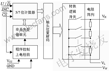
Figure 1 Internal structure of X931x series DCP
The volume control of each channel of the system is composed of two X9313 and one X9312. Figure 2 is a functional connection diagram of three digital potentiometers. The U / D and INC terminals of all DCPs are connected together, while the chip select terminals CS each occupy an MCU port. This kind of hardware connection can easily realize the volume control of four channels or more channels. In order to be consistent with the common digital volume adjustment habits, it is best not to retain the three-key control method of the general DCP, but only need to set up the UP / DOWN two sets of keys to directly control the volume increase or decrease. The connection between the UP / DOWN button and the MCU should be set with a software delay debounce algorithm to eliminate the jitter when the button is input, and the button jitter is no longer considered between the MCU and DCP.
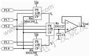
Figure 2 Schematic diagram of system connection
Resolution extension
Ra and Rb are connected in parallel at both ends of the input signal Vin, and the number of taps is 32. The outputs of Ra and Rb are set for the Rc port voltages VH and VL. Ra is always higher than Rb by a position interval, so that a total of 31 input signal voltage changes from 1 / 32Vi to 31 / 32Vi can be added to both ends of Rc. Since Rc selects a 100-tap DCP, the Vin linear voltage value of 31 × (100-1) = 3069 can be obtained at the Rc output.
As the sliding end of Rc moves up and down, the positions of Ra and Rb are adjusted accordingly under the control of the MCU. During the upward movement, suppose the value of the upward movement of the sliding end of Rc is added to the current position value to be M. If M is less than 100, it means that only the sliding end of Rc is moving, and the position of the sliding contact of Ra and Rb is unchanged; if the value of M exceeds 100, the contacts of Ra and Rb are moved up by 1 sliding position, Rc The sliding end of returns the contact position determined by the actual value obtained after M minus 100. Similarly, during the downward movement of the tap, if the sliding end of Rc needs to move down below the tap 0, the sliding ends of Ra and Rb also need to move down simultaneously by 1 bit to maintain the balance of the actual adjustment steps of the potentiometer.
The tap output end of the potentiometer Rc is provided with a first-level voltage follower, which can reduce the influence of the parallel load on the voltage division coefficient after the cascade. The sliding process of the potentiometer contact belongs to a discontinuous step adjustment method, so the resistance value of Rc does not continuously change but has the desired output after the sliding end is adjusted in place, which will cause some small jumps in the output voltage. However, because the absolute increase of the input signal Vin is not large, and the resolution of the entire potentiometer expansion system is very high, we can parallel a small capacitor C1 of 1000 ~ 2200pF to the ground at the sliding output of the Rc potentiometer. To reduce the output voltage fluctuation.
The above-mentioned idea of ​​potentiometer resolution expansion has high feasibility and portability. It has been used in our system design scheme of a programmable gain programmable high-speed amplifier, and has achieved good results.
Resistance value indexing
The exponential processing of DCP is implemented by software, and no additional hardware is required. Because the function operation function of the general single-chip microcomputer is very limited, in terms of algorithm, the number of contact movement steps required for each level switching of the potentiometer is stored in the single-chip microcomputer ROM in the form of an array. When the resistance value is adjusted, the MCU obtains the actual offset of each DCP based on the UP / DOWN state of the button and the current order value, and then the MCU controls the DCP to perform the corresponding step switching action. Considering the actual resolution of 3069 levels, the system has set a total of 24 steps from zero to full-scale output, which is better than the 18 to 21 steps of mainstream mechanical step potentiometers on the market. Refer to Table 1 for the relationship between the number and the offset of the potentiometer tap. It is not difficult to see from the table that the system expands the DCP to a high resolution of 3069 precisely to adapt to the precise analysis of the step value of the potentiometer resistance during the exponential adjustment process.
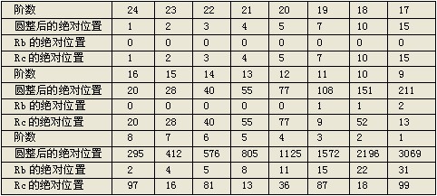
Table 1 The relationship between the order and the offset of the potentiometer tap
X9312 and X9313 cannot directly read the current position of the sliding end from the on-chip storage unit. Therefore, in order to memorize the actual position of each digital potentiometer sliding contact, you must set variables in the program for the contact position of different potentiometers Remember.
Conclusion
The solution of the high-resolution exponential digital potentiometer realizes the application of the universal linear digital potentiometer in the audio system at a lower cost, and has good engineering application prospects and promotion value. In addition, since the exponential high-resolution expansion of DCP occupies very little system resources, the remaining port resources of the MCU can be used in the functional links such as volume status indication and infrared signal decoding to improve the system functions.
AC Contactor switch mainly used for making or breaking circuit at a long distance, suitable for controlling starting\stopping\reversing of AC motor. AC Contactor of korlen conforms to the requirement of IEC60947-4-1& GB14048.4 standards.
Except AC Contactor, there are many different types of low voltage electric appliances, such as Thermal Relay,Manual Motor Startor ,LED Light, Circuit Breaker, etc.
AC Contactor
AC Contactor,Magnetic Contactor,Wafer Style Valve
Wenzhou Korlen Electric Appliances Co., Ltd. , https://www.korlenelectric.com