60Hz time base signal generator
This article refers to the address: http://
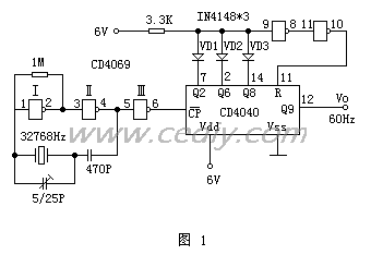
The circuit is composed of 12 binary serial counters/dividers 
In the circuit, the gate I and the gate II of the CD4069 constitute a crystal oscillator with an oscillation frequency of 32768 Hz. The output is shaped by the door III of CD4069 and sent to the end of CD4040. The output of CD4040 is set by the diodes VD1~VD3 with a frequency coefficient of 21+25+29=546. After frequency division, a 60Hz clock signal can be output to the digital clock integrated circuit on the output terminal Q9.
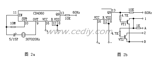
Figure 2a is another 60 Hz pulse generation circuit. It consists of an integrated circuit CD4060 and a crystal oscillator with a resonant frequency of 30720Hz. The CD4060 is a 14-bit binary serial counter, divider and oscillator. The CD4060 is divided into two parts, one of which is a 14-stage counter/divider with a division factor of 16~16348. The other part can be combined with an external resistor and capacitor to form an RC oscillator, and it can be combined with an external crystal to form a high precision. Crystal oscillator. This circuit uses an external 30720Hz crystal oscillator to form a crystal oscillator. The oscillating signal is divided by the internal frequency of CD4060 and output an accurate 60Hz frequency signal (30720÷29=60Hz) at the Q9 end.
When the circuit is used with a double-negative digital clock, the circuit of Figure 2b can be used for polarity switching. VT1, VT2 select NPN type triode, such as 9013, 8050, etc., the A terminal is connected to the positive power supply, and the B terminal is connected to the negative end of the power supply. When the circuit is used with the dual-yang digital clock, VT1 and VT2 select PNP type triode, such as 9012, 8550, etc. In the figure, the A terminal is connected to the negative power supply, and the B terminal is connected to the positive power terminal.

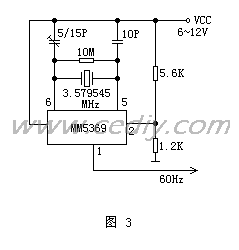
3 is a 60 Hz pulse generating circuit composed of a 60 Hz pulse generator ASIC MM5369 (8-pin DIP package) and a crystal oscillator having a resonant frequency of 3.579545. It is often used to provide a 60Hz frequency with a digital clock. After the oscillating signal is processed by the partial frequency in the MM5369, it is output from the 1 pin, and the frequency is quite stable. The circuit is powered by a 6~12V power supply. When the power supply voltage is lower than 6V, the operational reliability is deteriorated. In special cases, the resistance of R3 in the circuit can be changed to about 100 ohms, which can reduce the normal working voltage of the circuit to 4.5V.

The above two circuits are suitable for the whole circuit of the negative grounding, and also for the circuit system with the positive grounding, which can be used in the design.
Figure 4 is a 60 Hz clock circuit composed of two CMOS integrated circuits and a quartz crystal. Quartz crystal and CD4060 form the oscillation and frequency division part, and BG1 and CD4017 form the counting and distribution part. The 1024 Hz, 4 Hz square wave signal is output on the 5th and 2nd feet of the CD4060, the 1024 Hz input is applied to the CD4017 pin 14 as a clock pulse, and the 4 Hz signal and the signal assigned to the CD4017 pin 11 constitute an "OR gate" signal and then input to Pin 15 of CD4017 is used as a reset signal. During the 1/4 cycle of the second leg of the CD4017, the CD4017 is reset at a high level; the CD4017 receives 128 pulse signals at a low level, and the 9 pulse signals CD4017 are reset once, so that only the 15 pulse signals of the second pin of the CD4017 are allocated. A total of 60 pulse signals of the second pin of the CD4017 are allocated in one second, thereby obtaining a practical clock 60 Hz standard time base signal.

The calibration of the quartz oscillation frequency can be measured by the frequency meter. The 9th pin of the CD4060 should be 32768Hz. If it is deviated from the micro-adjustable variable capacitor, it should be corrected.
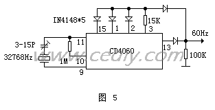
Figure 5 is a 60 Hz time base signal generator consisting of a piece of CD4060 . The first few are the most practical time-base signal circuits.

Fiber Optic Pigtail is a piece of fiber optic cable with only one Fiber Optic Connector, it is typically used to link fiber optic cable with other fiber optic equipment. The connector side is mainly in charge of the connections while the other side is melted together with fiber glasses to achieve minimum insertion loss. We provide a full range of fiber optic pigtails, such as SC, SC/APC, ST, FC, FC/APC, LC, LC/APC, E2000 and E2000/APC for both single mode and multi mode. These pigtails can be used with various types of fiber optic terminations, including SC, FC ST, LC, MU, MTRJ, MPO etc.
Pigtail Cable,Single Mode Fiber Pigtails,Pigtail ST,ST Fiber Optic Pigtail
Chengdu Xinruixin Optical Communication Technology Co.,Ltd , http://www.xrxoptics.com