Ward pager principle and circuit diagram
With the development and application of wireless technology, the ward pager system can receive call information in instant messaging and mobile. Some pagers have been developed and manufactured on the basis of FM wireless technology. It combines the system developed by single chip microcomputer and computer technology. .
Generally, it works as follows: a pager is placed in each hospital bed. When the patient needs service, the button of the pager can be displayed by simply pressing the button of the pager, and the receiver can display the bed number and give a music prompt, and the medical staff can The prompt message knows the exact bed to be serviced and provides the appropriate service.
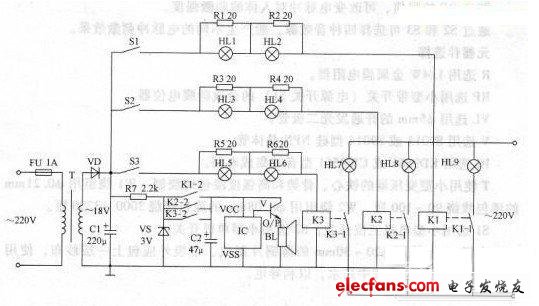
Ward pager circuit schematic
The following is a detailed analysis of its circuit principle and circuit design and implementation principle (the ward call system circuit diagram) by combining the circuit of one of the ward callers. It mainly consists of the following three parts: power circuit, trigger control circuit and sound and light call circuit. These three parts are independent and interconnected, which completes the function of the whole system. Let's talk about the selection of the parameters of the electronic components and electronic components used in the circuit diagram.
A, VD selects 1 N5401 type silicon rectifier diode;
B, C1 select aluminum electrolytic capacitors with a withstand voltage of 35V;
C, C2 select aluminum electrolytic capacitors with a withstand voltage of lOV;
D, VS selects 1/2W, 3V silicon steady voltage diode;
E, R1~R6 select 2~4W wirewound resistors;
F, R7 select 1/2W metal film resistor;
G, IC selects KD9300 or C W9300 type music integrated circuit;
H, K1~K3 select JRX-13 F type 6V DC relay;
I, BL selects 0. 25W, 8 Ω electric speaker;
J, V selects the Model 59013 silicon NPN transistor;
K, T select 5VA, the secondary voltage is 18V power transformer;
L, S1~S3 select button self-locking switch or boat switch;
M, HLl ~ HL6 are selected 6.3V, 0. 1 A when the red indicator bulb;
N, HL7 ~ HL9 select 220V, 10 ~ 20W red light bulb;
The principle of Power Supply is analyzed as follows:
In the circuit, the power supply circuit is composed of a fuse FU, a power transformer T, a rectifier diode VD, a filter capacitor C1, a current limiting resistor R7 and a Zener diode VS; the trigger control circuit is composed of S1~S3 (bed switch of the ward), and a resistor R1~R6 and indicator lights HL1~HL6 and relays K1~K3; sound and light calling circuit consists of indicator lights HL7~HL9, K1-K3 normally open contacts, capacitor C2, music integrated circuit IC, transistor V and speaker BL composition.
After the AC 220V voltage is stepped down by T, VD rectified and C1 filtered, 18V DC voltage is generated, one is used as the working power of the trigger control circuit; the other is regulated by R7 and the VS is regulated to 3V DC voltage, which is used as the working power of the IC. When S1~S3 are not pressed, HL1~Hl9 are not lit, and BL does not sound. When a switch in S1-S3 is pressed, the relay of the road is energized and closed, and the indicator light is illuminated; at the same time, the IC is energized, and the music electric signal outputted by the 0/P terminal is amplified by V, and the BL is driven to emit music.
For example, when S2 is pressed, HL3 and HL4 are lit, so that K2 is energized and pulled, and its normally open contacts K2-1 and K2-2 are turned on, so that H L8 is turned on, and BL emits a musical sound.
Ward pager features and features
A, no wiring, easy installation and maintenance;
B, improve the service response speed, can guarantee on-call;
C, not only can solve the bedside call, but also solve emergency calls in the bathroom, activity room, etc.;
D, the procedure of the patient call service is simpler, just click the button used;
E. Medical staff can carry it with them and provide services anywhere in the venue;
F. It is possible to achieve communication without loud noise and create a good medical environment;
G. Reduce labor costs, a medical staff can monitor several wards;
H. Reduce management costs, eliminate the need for multi-level human monitoring, improve management efficiency, and save management personnel;
I, two-way call, dual-function call, host multi-function display, multi-level care settings, fault self-test alarm, emergency call function, etc.
How to use the ward caller
A. The patient initiates a call according to the corresponding button of the wireless pager, and finds a staff member;
B. It is possible to know which room or which bed to call through the LED screen display class, and where is the type of call;
C. You can know the content of the call through the digital information machine that you carry with you, and there are various prompts such as vibration and music.
D. Install call supervision management software to query the call record;
E, management personnel can also be equipped with wireless dispatch controller or wireless keyboard pager, dispatch service personnel and group call alarm
Equipped with A standard AC inlet IEC320-C8 (have no earth pin), the single phase ac to dc power adapters is developed the output power range to 12 wattage. Our green power range focusses on high active mode efficiency and low no load power consumption, complying with the latest global energy efficiency standards. 3 Years Warranty.
Wall plug Adapter,Cctv Adapter,Ac Adapter for POS,Ac Adapter,12V Adaptor,Dc Adapter
Shenzhenshi Zhenhuan Electronic Co Ltd , https://www.szzhpower.com