USB3.0 technical specifications and signal integrity analysis
First, SuperSpeed ​​USB interface
The USB 3.0 era has just begun.
The USB 3.0 standard was developed by Intel and HP, NEC, NXP, Microsoft and Texas Instruments. The goal of USB 3.0 is to provide ten times the current bandwidth. With the addition of two pairs of high-speed lines, the "Superspeed" mode can reach about 4.8. Gbit/s (600MB/s) and may use fiber optic connections.
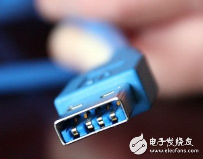
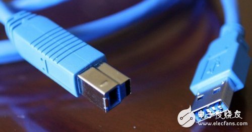
The technical specifications for USB 3.0 were released on August 13, 2008, and commercial products are expected to be released in 2009 or 2010. USB 3.0 has added 5 contacts, two for data output, two data inputs, and a send list section for data distribution. The new contacts will be placed side by side with the current four contacts. The USB 3.0 tentative power supply standard is 900mA, which will support fiber transmission. The USB 3.0 design is compatible with USB 2.0 and USB 1.1 versions and uses a more efficient protocol to save energy.
So why does USB3.0 have such a magical charm, how does it work?
Second, USB3.0 specification analysis
The USB technology that many people see is just interfaces and cables, but few people care about the way data is transmitted and processed in the USB interface. In today's desktops and laptops, as a host computer, they all contain a host controller. This small chip has a series of logical pipes that manage the transfer of various data between the host and the device. The current Hi-Speed ​​USB interface, the USB 2.0 interface, uses a half-duplex architecture, meaning that data transmission is only one-way. First, the peripheral device sends a signal to the computer, and then the computer sends a signal to the peripheral device, and the two mutually transmit the information at the same time.
In the USB 3.0 specification, it will have its own dedicated data path, dedicated data transmission lines and independent data receiving lines. Therefore, when data communication between the host and the peripheral is performed, full duplex can be realized. Both the host and the peripheral can send and receive data simultaneously.
In addition, the data transmission rate will be greatly improved, and the data transmission capability of 5Gb/s can be realized, and the data throughput of 4.7Gb/s can be realized in each direction. In the current fastest USB 2.0 specification, only one-way 480Mb/s can be implemented.
Whether it's a host or a peripheral, all data transfers can burst at the same time. These dedicated data transceiving channels minimize data turnaround time and they can simultaneously issue operational requests. The USB 3.0 interface is backward compatible with previous USB 2.0 and USB 1.1 interfaces.
Third, USB3.0 pin contact analysis
In order to be backward compatible with the USB2.0 specification and to greatly increase its bandwidth, USB3.0 has set up two sets of data transmission mechanisms in one cable. One set is convenient for ordinary USB2.0 interface, and one set is dedicated for transmitting and receiving high-speed transmission channels.
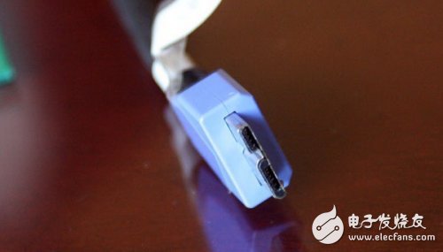
As shown in the figure, this is the USB 3.0 Micro B interface, pin 1 is power supply (VBUS), pin 2 is USB2.0 data - pin 3 is USB2.0 data +, pin 4 is USB On-The-Go ID Line, pin 5 is ground (GND), pin 6 is USB3.0 transmit data line - pin 7 is USB3.0 transmit data line +, pin 8 is ground (GND), pin 9 is USB3.0 Receive data line -, pin 10 is USB3.0 receive data line +.
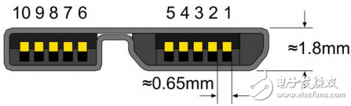
USB 3.0 Micro B
USB3.0 includes standard A / standard B / Micro specific pin definitions are as follows:
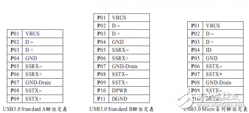
Table 1 USB3.0 standard A / standard B / Micro pin definition
Fourth, USB3.0 signal integrity
The signal integrity requirements of USB3.0 are compared with USB2.0. The signal integrity specification of USB3.0 is much higher than that of USB2.0. See Table 2 for details. Also refer to SuperSpeed ​​Electrical Requirements for USB 3.0 Specification 5.6.1.
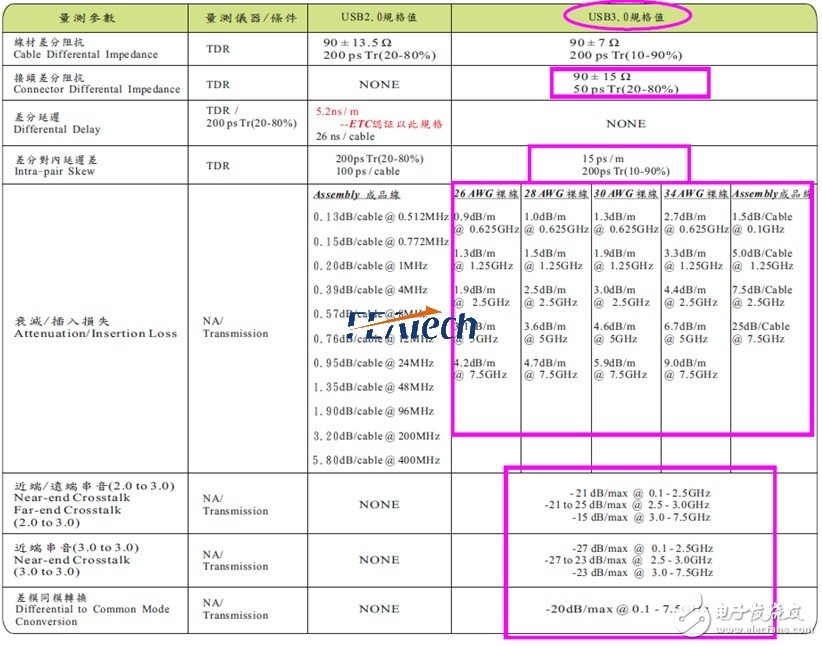
Table 2 Signal integrity of USB3.0
At present, the results of design, high-frequency signal analysis and testing of USB3.0 from various connector providers show that Near-end Crosstalk and DifferentTIal to Common Mode Conversion are compared. Difficult to meet regulatory requirements, further simulation analysis is needed to improve signal integrity performance.
7.2 Volt Battery Pack,Best 18650 Battery Charger,18650 Battery Size
Ji'an Powercom New Energy Co., Ltd. , https://www.expowercome.com