Projector lifting control design based on dual processor
Abstract: A design scheme of projector lifting control based on Atmega8 and Stm32F101 dual processor is proposed. The circuit composition, function and software flow are introduced. Among them, Atmega8 is responsible for data acquisition, Stm32F101 realizes control of the motor, and the processor communicates through the I2C bus. The system uses infrared remote control or external button input device control, or can be controlled online with a PC. The test verifies that the design scheme is correct and effective, and the fixed point accuracy meets the practical requirements.
This article refers to the address: http://
1 Introduction
The projector lifting control system consists of Atmega8 data acquisition circuit, Stm32F101 control circuit, motor rotation number detection module, infrared remote control receiving module, external button module and external anti-jamming circuit. The goal is to control the rise and fall of multimedia devices such as projectors. In the solution, the upper limit and the lowest point of the projector can be set at any time. After the setting is completed, no matter which position the projector is, the highest point can be reached when the up button is pressed, and the lowest setting can be reached when the down button is pressed. Point, stop motion when you press the stop button. The operation mode is combined with coarse adjustment and fine adjustment. When the operation key is pressed for 3 seconds, the projector continuously rises or falls, and when the hand is released, it stops, mainly used for coarse adjustment; when the operation key is short pressed, the projector automatically stops after rising or falling a certain distance. For fine tuning. When the settings are completed, save the settings with the Save button. If the settings are not saved, the set points are invalid. The infrared remote control can be set to both operating parameters and lifting control.
2 basic control methods
The key of the control system is that the projector can be controlled to be lifted to any position. The lifting process is realized by the motor. The linear distance of the lifting corresponds to the number of rotations of the motor, and the control of the number of revolutions of the motor is realized. control. The technical breakthrough of this scheme is to convert the precise linear distance control into the control of the number of revolutions of the motor. The rotation of the motor is one millimeter corresponding to the lifting straight line distance. The linear distance control accuracy of this scheme is one millimeter, that is, the rotation of the motor is realized. A circle of digital control. In the motor control module, two infrared sensors are used to realize the number of rotations and rotation directions of the motor. The signals output by the sensors are collected by the two I/O pins of the Atmega8. The level combination signal of the pins changes state to 00,10,11. , 01 (clockwise) or 00, 01, 11, 10 (counterclockwise). This article uses the motor _state structure to represent the state of the motor. The meaning of each element in the structure is as follows:
It is possible to know whether the motor rotates by comparing the values ​​of the first two elements of the structure; the 3,4 element comparison can accurately locate the projection position, and when it is equal, an interrupt is generated to command the motor to stop rotating; in the last 2 elements, when the two pins are 00 to 10, motor _ bit _ L 0th position one, 10 to 11, when the first position is one, 11 to 01, the second position is one, the first position is from 01 to 00, the third position is one, so when the lower 4 bits A total of 1 means that the motor rotates one turn counterclockwise, and a clockwise turn turns it by motor _ bit _ R.
3 control system hardware design
The control system is generally divided into two parts: signal acquisition and motor control.
For example, Atmega8 on the right side of the system block diagram is mainly used for signal level acquisition of infrared sensors. When Stm32F101 controls the motor to move up and down, the motor number detection circuit will input signals to the Atmega8 through the infrared sensor to judge the operation of the motor. On the left is the lifting section of the Stm32F101 control motor. The commands can be input by infrared remote control or by pressing the button after connecting to the PC. When the Atmega8 captures the infrared sensor signal level, it can transmit information through the I2C bus and the Stm32F101. When the projector reaches the destination, it sends an interrupt signal to interrupt the Stm32F101 and handle related operations. As shown in the figure, the internal data of two E2PROMs can be easily read and written through the serial port. The power-down save module uses the CAT24WC16, which automatically saves the state parameters of the motor power-off time even if it suddenly loses power during operation, that is, saves the motor_state structure variable.
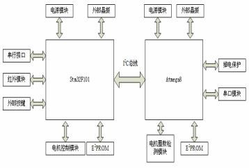
Figure 1 controller system hardware structure diagram
3.1 Motor lap detection unit
This unit is in an important position in the whole system. At the end of the motor shaft, a semi-circular iron piece is placed between the transmitting end and the receiving end of the infrared sensor. When the motor rotates, the iron piece rotates. There are two infrared sensors in the lap detection unit, each of which is composed of a transmitting end and a receiving end. When the transmitting end and the receiving end are blocked by the semi-circular iron piece, the output signal is low level 0. When it is not blocked, the output signal is high level. 1. Because it is a semi-circular iron piece, as the motor rotates continuously, the Atmega8 two pins The infrared sensor signal is received and the input levels of the two pins are continuously and cyclically detected. When the input level of the two pins does not change, it means that the motor does not rotate. When the change state is 00, 10, 11, 01 or 00, 01, 11, 10, it indicates that the motor rotates. The status sequence reflects the motor rotating clockwise or counterclockwise.
3.2 Motor Control Module
Figure 2 is a hardware schematic of the Stm32F101 for motor control.
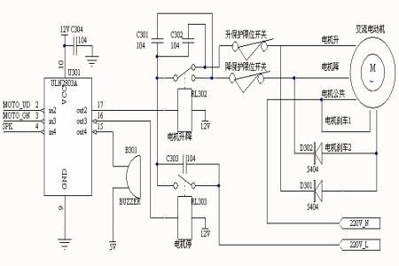
Figure 2 Motor control hardware structure diagram.
In the figure, ULN2803A is a Darlington drive device controlled by Stm32F101, MOTO_UD, MOTO_ON, and SPK is directly connected to Stm32F101. Their functions are to control motor lift, control motor operation or stop, and control buzzer stop. When the relay RL303 is working, the motor works at 220V AC, otherwise it stops working. When the relay RL302 is normally open, it is known from the figure that the motor is controlled to rise, and the normal closing is to lower the operation of the motor. In order to improve the safety of the motor, the lifting protection is also adopted. In the figure, two limit switches are connected, which are the lifting and lowering limit protection respectively, that is, when the limit point is reached, the limit switch is disconnected, causing the motor to stop working. To the role of the protection circuit.
4.2 Stm32F101 Software Process
After the power-on reset, the system is initialized, and the main function loops through three sub-functions, waiting for an external control command input. When receiving any kind of external command, Stm32F101 causes Atmega8 to generate I2C interrupt and transfer relevant data. After Atmega8 responds normally, STM 32F101 performs control motor operation. The program flow chart is shown in Figure 6.
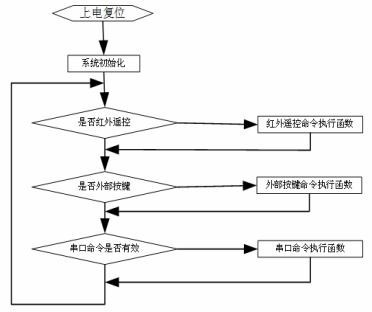
Figure 6 Stm32F101 software flow chart.
5 Analysis of experimental results
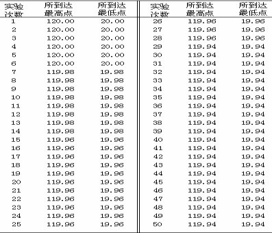
First set the lowest point and the highest point of the projector to 20.00cm and 120.00cm respectively. In the experiment, the projector is always powered after the projector is interrupted for a while, and the lowest point and the highest point reached by the projector are repeatedly recorded. Experimental data See Table 1. From the test results, the measurement error is within 1mm, and the test data will shift downward as the number of experiments increases. It can also be tested that when the projector is interrupted during power-up, the test data will shift upwards as the number of experiments increases. Therefore, in practical applications, the error of the set point reached by the projector can be guaranteed within 1 mm.
Table 1 Experimental test data cm
6 Conclusion
The technical breakthroughs of this program are:
First, Atmega8 captures the infrared sensor signal level two states 00,10,11,01 and 00,01,11,10 and related algorithms, and correctly and quickly acquires the motor's rotation state and number of revolutions. The precise linear distance control translates into control of the number of revolutions of the motor.
Secondly, with dual processors, Atmega8 is responsible for signal acquisition and analysis, and Stm32F101 is responsible for motor control, which makes the real-time performance higher and the response speed faster, thus the stability and accuracy are obviously improved, fully satisfying the multimedia equipment such as projectors. Positioning requirements.
3.3 External input module
Figure 3 shows the external key input module. The keys_1, key_2, and key_3 are connected to the Stm32F101 pins respectively. When the key is pressed, the key input is 0. When more than one key is pressed at the same time, it is considered invalid. The valid modes correspond to the three states of 110, 101, and 011, respectively. When any one of the keys is pressed, the LED is turned on, and the optical signal is emitted as the base input of the triode, and the triode is turned on, corresponding to the low level of the Stm32F101 pin, thereby correspondingly processing. The use of optocoupler enhances the anti-interference ability.
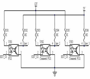
Figure 3 External button structure diagram.
Figure 4 is the interface diagram of the infrared remote control decoding module, D0, D1, D2, D3 connected to Stm32F101. The infrared remote control module uses a decoding ASIC (BM2272) and a coding circuit (BM2262) to use a decoding ASIC. In Figure 4, the BM2272 module receives a series of addresses and data sent by the BM2262 infrared transmission mode, and performs two consecutive comparisons through the address bits. If no error codewords and unmatched words are found, the input data is decoded and transmitted to the corresponding The data pin is output while the VT pin outputs a high and low pulse to indicate an effective emission.
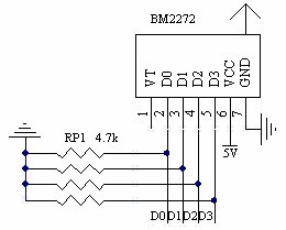
Figure 4 Interface diagram of the infrared module remote control decoding module.
4 software design
The overall software design is divided into Atmega 8 software design and Stm32F101 software design. After receiving the command, Stm32F101 enters the relevant processing function, performs different operations according to the command, and communicates with Atmega8 through the I2C bus.
4.1 Atmega8 Software Process
After the start, the system initialization is first performed, including initializing the timer, serial port, I2C, etc., and then reading the motor parameters saved from the power-down time from the E2PROM, completely restoring the state when the motor is powered off. After entering the main function, each sub-function is executed cyclically. When the motor rotates, the structure variable is updated according to the collected level signal, and a motor_data element is added or subtracted by one turn. When motor_data is equal to motor_over, an external interrupt signal is generated to cause Stm32F101 to be interrupted. Execution of the program in the body stops the motor.
Whenever power is lost, it will immediately enter the power-down save program, write important parameters into the E2PROM, and restore the parameters of the motor power-down time at the next power-on. Since Stm32F101 is the main I2C, when Atmege8 receives the I2C data, it generates an I2C interrupt, saves the data to the corresponding array, and sets the relevant flag. When the loop to the I2C interrupt flag is 1, it immediately enters the processing command function, and the interrupt is satisfied when the condition is met. Stm32F101, program flow chart shown in Figure 5.
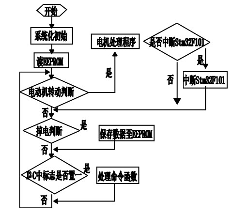
Figure 5 Atmega8 software flow chart.
Glass Insulator is used to support and insulate electrical wires. The most widely used in the production line are tempered glass insulator. Now days Glass Insulator For High Voltage has become popular in transmission and distribution system. Annealed tough glass is used for insulating purpose. Glass insulator we have Standard Type Disc Insulator, Blue Glass Insulators ,Fog Type Disc Insulator and Open Air Profile Disc Insulator, it has numbers of advantages over conventional Porcelain Insulator .
Advantages of Glass Disc Insulator
1. It has very high dielectric strength compared to porcelain2. Its resistivity is also very high
3. It has low coefficient of thermal expansion
4. It has higher tensile strength compared to porcelain insulator
5. As it is transparent in nature the is not heated up in sunlight as porcelain
6. The impurities and air bubble can be easily detected inside the glass insulator body because of its transparency
7. The surface of the glass insulator has high mechanical strength,it profect the surface from cracking.Compared with porcelain insulator,the aging process is much slower
8. Glass is cheaper than porcelain


 We warmly welcome friends both domestic and abroad to visit our company, for more details about glass insulator, if you have any questions, please contact with us directly.
Glass Insulator
Glass Insulator,Glass Disc Insulator,Glass Insulator For High Voltage,Blue Glass Insulators
FUZHOU SINGREE IMP.& EXP.CO.,LTD. , https://www.cninsulators.com