Discussion on Circuit Design of Low Voltage and Low Quiescent Current LDO
Abstract: Design a linear low-voltage regulator with low voltage and low quiescent current. Traditional LDOs have independent bandgap reference voltage sources and error amplifiers. In an innovative LDO, the bandgap reference voltage source and the error amplifier are combined into one, thus achieving low quiescent current consumption. The design is simulated in a CSMC 0.5 μm double-well CMOS process. The LDO has a quiescent current of only 1.7 μA under light load and a maximum output transient voltage of 9 mV.
With the rapid development of handheld smart terminals in the past few decades, Low Drop-out Regulator (LDO) has the advantages of low power consumption, high power supply rejection ratio, small size, and simple circuit design. Get a lot of applications. LDOs work most of the time in low-load applications, so their quiescent current consumption at low load conditions determines battery life. Today's LDO trends are low voltage, low quiescent current to extend battery life. However, low quiescent current can cause instability, resulting in large transients in output voltage, which must be reasonably compromised between quiescent current and output transient characteristics. Compared with the traditional LDO, the discrete structure of the bandgap reference voltage source and the error amplifier, this paper presents an innovative structure of LDO, combining the bandgap reference voltage source and the error amplifier into two modules, so it is easier to achieve low Quiescent current consumption, low transient voltage variation.
1 LDO circuit analysis
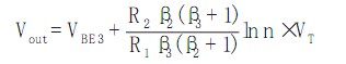
Figure 1 shows a reduced-structure LDO that includes only four main current branches: gain stage, buffer stage, and two PTAT current sources.
Compared with the traditional structure LDO, the simplified structure combines the bandgap reference voltage source and the error amplifier into one, so the quiescent current consumption of the circuit can be reduced to about 1 2 under other conditions.
This circuit has two disadvantages: the output voltage is not adjustable for the bandgap reference voltage; the NPN transistor is required, and the NPN transistor is not present in the standard CMOS process. Since today's SoCs tend to work in low voltage environments, this configuration can have ample applications. The second problem is that in the single-chip design, the double-well CMOS process is used, and only one mask process is added, and the cost is not increased much, so the practical application of the two problems is not obvious.
1.1 Bandgap Reference Voltage Analysis
The triode base shot voltage and the thermodynamic voltage have negative and positive temperature coefficients, respectively. Therefore, the principle of the bandgap reference voltage is to superimpose the triode base shot voltage and the thermodynamic temperature voltage to reach a zero temperature coefficient at room temperature.
In a reduced LDO structure, transistor Q3 and resistor R2 define a bandgap reference voltage and flow through R2 to a PTAT current. The current flowing through transistor Q1 is mirrored. Transistor Q3 is biased to the collector current. Therefore, in the loop, transistors Q1 and Q3 will be adjusted to the same base shot voltage value. Especially in the case of a relatively high loop, this adjustment is quite accurate. Therefore, transistors Q1, Q2, and Q3 have the same collector current by properly designing resistors R2 and R3. therefore:
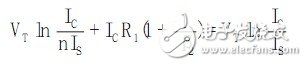
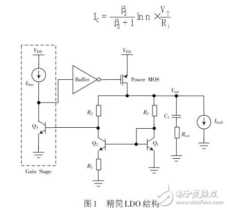
Where: IS is the triode saturation current; β2 is the current gain of transistor Q2; n is the area ratio of the emitters of transistor Q2 and Q1. The PTAT current can be obtained by the formula (1):
Therefore, the output voltage value can be obtained by superposing the base emitter voltage of the transistor Q3 and the R2 voltage:
Adjust the resistance ratio to make the VT coefficient 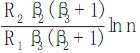 A value of 17.2 gives a bandgap reference with a zero temperature coefficient.
1.2 LDO frequency analysis
The reduced structure LDO contains three low frequency poles, which are respectively at the output of the gain stage, the output of the buffer stage and the output node of the LDO, as follows:
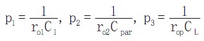
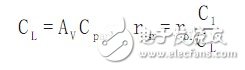
Where: ro1 and C1 are the gain stage output resistance and load capacitance respectively; ro2 is the buffer stage output resistance; Cpar is the power tube input capacitance; rop is the equivalent resistance of the LDO output stage; CL is the output load compensation capacitance. In order to ensure that the LDO has a good output transient characteristic, the value of CL is generally large, so the pole p3 is the main pole of the LDO loop. The collector current of transistor Q3 is biased to PTAT current, so the output impedance of the gain stage does not change much with the output load current and input voltage, and the load capacitance of the gain stage is mainly determined by the buffer stage input capacitance, so the pole p1 position is relatively stable, so A zero compensation of the left half plane can be used. Similar to the traditional LDO, this paper uses a resistor resr and the output compensation capacitor in series to obtain a left half plane zero:

Based on the above analysis, the open-loop transfer function of the reduced structure LDO is:
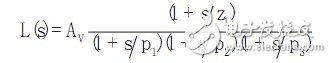
In the middle  Where: gmQ2, gmQ3 and gmp represent the transconductance of transistors Q2, Q3 and the power transistor, respectively; Rπ 3 is the input resistance of transistor Q3. When p1 and z1 match accurately, the LDO loop has only two low frequency poles p2 and p3. Therefore, in order to obtain a phase margin of 60°, you must:
This Automation curtain is specially designed for automation industry. SDKELI LSC2 light curtain is designed for automation field, with small size, compact structure and strong anti-interference ability, and the product meets IEC 61496-2 standards. The Automatic Light Curtain is with reliable quality and very competitive price. It has been used in many factories and has replaced curtains from Sick, Omron, Banner, Keyence, etc.
Automatic Light Curtain,Laser Light Curtain,Automation Light Beam Sensor,Automatic Infrared Beam Sensor,Infrared Beam Curttain Sensor,Infrared Beam Sensor
Jining KeLi Photoelectronic Industrial Co.,Ltd , https://www.sdkelien.com