Design of photoelectric encoder detector based on Arduino development environment
0 Preface
Arduino is an electronic product development platform based on single-chip system. Its software and hardware systems are highly modular, and the software system is completely open source. The hardware system is also highly modular. There are switching input/output modules, various analog sensor input modules, bus sensor input modules, and network communication modules on the periphery of the core control board [1-2]. Arduino Have their own unique programming language. The grammar rules are similar to the C/C++ language. The IDE environment and language parameterize some parameters related to the MCU and the hardware, and package them well. The ports are packed, and the registers, address pointers and the like are basically ignored. The difficulty of software development. Therefore, developers can be programmed without knowing their hardware structure to realize the designer's design intent and creativity [3].
This paper proposes a design scheme of photoelectric encoder detector based on Arduino development environment, which can judge the quality of photoelectric encoder and realize the pulse counting of photoelectric encoder in forward and reverse rotation.
1 overall design
The detector is mainly composed of a conditioning circuit, an Arduino control board, a liquid crystal display circuit, etc., as shown in FIG.
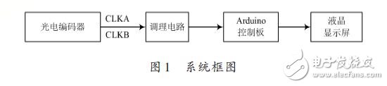
CLKA and CLKB are two encoded signals with phase difference of 90° output from the photoelectric encoder. The conditioning circuit is used to perform signal processing such as shaping and filtering on the two signals, and finally sent to the Arduino control board. The Arduino control board is used to count the number of optical encoder pulses, and to distinguish between positive and negative pulse signals. The liquid crystal display circuit is used to display the detected parameters, and at the same time select and control different types of photoelectric encoders.
2 hardware part design
2.1 conditioning circuit
The signal conditioning circuit is used for detecting the conditioning of the signal, mainly by processing the AC signal to be tested, filtering, amplifying, strobing, RMS conversion, limiting, etc., and sending it to the microcontroller for measurement.
Figure 2 is a block diagram of the conditioning circuit. The two sinusoidal signals A and B with phase difference of 90° output by the photoelectric encoder are converted into a square wave signals of a and b by Schmitt trigger. A is divided into two groups: one way through the differential circuit, the pulse signal d is formed on the rising edge of the square wave, and then output by the gate circuit to form a forward rotation pulse, and the other path is formed by an inverter to form an inverted square wave c, and then differentiated. The circuit forms a pulse signal e, and the square wave of the inverted pulse gb output by the gate circuit is directly connected to the control terminals of the two gate circuits as the strobe signals of the two gate circuits.
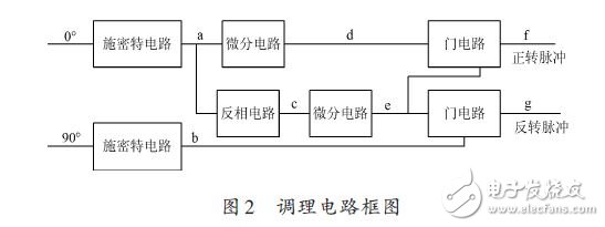
When the photoelectric encoder is rotating forward, the b group signal leads 90°, and its square wave positive half wave corresponds to the rising edge of the square wave without the inverter a group, the positive half wave makes the gate circuit strobe, and the d group pulse passes the gate. The circuit forms a forward pulse; and the rising edge of the c group square wave corresponds to the b group square wave negative half wave. At this time, although the differential circuit outputs the e pulse, the gate circuit is closed, and the inverted pulse g cannot be output. When the encoder is reversed The situation is just the opposite. The final output pulses are sent to the control detection circuit for counting.
2.2 Arduino Control Board
The detector uses the newly developed Arduino Due microcontroller from Italy. Arduino Due is a microcontroller board based on the Atmel SAM3X8ECPU. It is the first Arduino based on a 32-bit ARM core. Dues using a 32-bit ARM core are more powerful than other Arduinos that used an 8-bit AVR core: a 32-bit core can handle 32-bit data in a single clock. The control board consists of 54 digital I/O pins (12 PWM outputs), 12 analog input channels, 2 analog output channels (DAC), and I/O port total output current is 130 mA. 3.3 V port output capability 800 mA, 5 V port output capacity is 800 mA, FLASH 512 KB (user space can be stored in all spaces), SRAM 96 KB (two parts: 64 KB and 32 KB), clock rate [4-5] is 84 MHz .
Since the operating voltage of the Arduino due is 3.3 V and the I/O port can carry a voltage of 3.3 V, the 5 V pulse generated by the conditioning circuit cannot be directly processed. The detector uses a SN74lVC4245 chip to shape a 5 V pulse into a 3.3 V pulse.
2.3 liquid crystal display circuit
In this design, a programmable smart LCD (Programmable Smart LCD, PS-LCD for short) developed in China is used. PS-LCD is an intelligent display module that includes an LCD display, LCD controller, touch screen, human interface processing system and communication interface. It can be connected to an external control unit through an optional communication interface (eg 51 MCU, ARM). , DSP, PC, PLC, bus equipment, etc.) to achieve the system's human-computer interaction interface.
New Designer project, define interface resolution, interface switching effect and main interface; set background, add/set controls, define event actions, etc.; PS-LCD uses Java Script scripting language, Java Script is the most popular script on the Internet. Language, which exists in all web browsers around the world, enhances user interaction with Web sites and Web applications. The liquid crystal display screen displays the number of pulses collected by the microcontroller in real time through scripting and judges.
Use the LCD simulator to verify the interface effects and communication process and repeat the previous steps until you are satisfied.
As an advanced intelligent human-machine interface product, PS-LCD can easily and flexibly interact with external control units through the communication interface. Currently, PS-LCD supports two communication protocols: CTP (Cooky Talking Pro-tocol) protocol and user-defined (UserDefine) protocol. This detector uses the CTP protocol.
Optical fiber jumpers are used to make jumpers from equipment to optical fiber cabling links. There is a thicker protective layer, which is generally used in the connection between the optical transceiver and the terminal box, and is used in some fields such as optical fiber communication systems, optical fiber access networks, optical fiber data transmission, and local area networks.
Optical fiber jumper (also known as optical fiber connector) means that both ends of the optical cable are equipped with connector plugs to realize the active connection of the optical path; one end with a plug is called a pigtail. Optical Fiber Patch Cord/Cable is similar to coaxial cable, except that there is no mesh shielding layer. In the center is the glass core through which light propagates. In a multimode fiber, the diameter of the core is 50μm~65μm, which is roughly equivalent to the thickness of a human hair. The single-mode fiber core has a diameter of 8 μm to 10 μm. The core is surrounded by a glass envelope with a lower refractive index than the core to keep the optical fiber in the core. On the outside is a thin plastic jacket to protect the envelope.
The classification and overview of optical fiber patch cords are as follows
Optical fiber jumpers (also known as optical fiber connectors), that is, optical fiber connectors that are connected to optical modules, are also available in many types, and they cannot be used mutually. The SFP Module is connected to the LC fiber optic connector, and the GBIC is connected to the SC fiber optic connector. The following is a detailed description of several commonly used optical fiber connectors in network engineering:
â‘ FC-type fiber jumper: The external strengthening method is a metal sleeve, and the fastening method is a turnbuckle. Generally used on the ODF side (most used on the distribution frame)
â‘¡SC type optical fiber jumper: the connector for connecting the GBIC optical module, its shell is rectangular, and the fastening method is a plug-in latch type, without rotation. (Most used on router switches)
â‘¢ST type optical fiber jumper: commonly used in optical fiber distribution frame, the shell is round, and the fastening method is turnbuckle. (For 10Base-F connection, the connector is usually ST type. Commonly used in optical fiber distribution frame)
â‘£LC type optical fiber jumper: the connector to connect the SFP module, it is made by the easy-to-operate modular jack (RJ) latch mechanism
Patch Cord,Ftth Mm Patch Cord,Simplex Ftth Patch Cord,Sm Ftth Optical Patch Cord
Shenzhen Scodeno Technology Co.,Ltd , https://www.scodenonet.com