Design of FIR Filter Based on DSP
introduction
Digital signal processing is now widely used in communications and information systems, signal and information systems, automation, demand, military, aerospace, medical, and household appliances. In digital signal processing applications, filtering plays an important role, such as filter filtering, detection, prediction, etc., and filters are widely used. The design of the IIR digital filter preserves the excellent amplitude characteristics of some typical analog filters, but the phase characteristics of the filters involved are generally nonlinear, while the FIR filters can guarantee the amplitude characteristics and meet the technical requirements. It is easy to achieve strict linear phase characteristics.
1 FIR filter design based on window function method 1.1 unit impulse response
First, the unit impulse response hd (n) of the filter to be sought should be determined according to the technical requirements. If the frequency of the filter to be sought is given as Hd (ej), the unit sample response can be obtained by:

If the requirements of the passband stopband attenuation and the boundary frequency are given, an ideal filter can be used as the approximation function, and the inverse of the inverse of the ideal filter is used to find hd(n). If the ideal low pass filter is:

1.2 Transition zone and stopband attenuation
According to the requirements of transition zone and stopband attenuation, the shape of the window function can be selected during design, and the window length N is estimated. Let the transition band of the filter to be sought be represented by Δω, which is approximately equal to the main lobe width of the window function. Since the transition band Δω is approximately inversely proportional to the window length N. That is, N = A / Δω, where A is determined by the window form, for example, a rectangular window A = 4π, a Hamming window A = 8π, and the like. According to the transition zone and the stopband attenuation, the window function form is selected. The design principle is to select a window function with a narrow main lobe as much as possible while ensuring the attenuation of the stop band.
1.3 Calculation of unit sampling response:
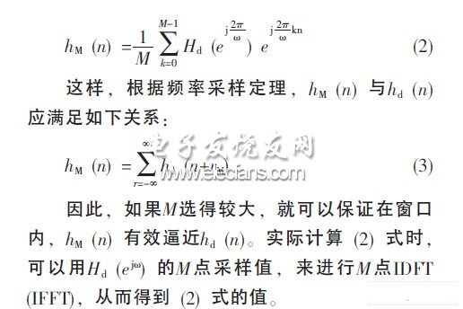
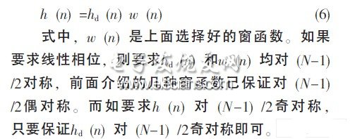
When calculating the unit sampling response h (n) of the filter, it can be done as follows:
The filter frequency response designed to check whether the technical indicators meet the requirements can be calculated by the following formula:
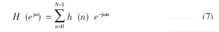
When calculating the above formula, the FFT algorithm can be used. If H (ejω) does not meet the requirements, then the above design may be repeated as needed, until the requirements are met.
2 DSP-based FIR digital filter implementation
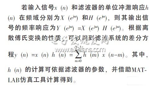
2.1 Difference equation of the filter system
SHENZHEN YINZHIGUAN DIGITAL TECHNOLOGY CO.,LTD , http://www.yzgmusiccrown.com