How to test sound and vibration
Based on PC data acquisition, measurement is performed through a combination of modular hardware, application software, and a computer. Although data acquisition systems have different definitions based on different application requirements, the purpose of each system to collect, analyze, and display information is the same. The data acquisition system integrates signals, sensors, actuators, signal conditioning, data acquisition equipment, and application software.
Sound and Vibration and IEPE Sensors Overview Vibrations are mechanically oscillating motions where a mass object occurs near the equilibrium point. Examples of common vibratory mechanical systems are spring-mass-damping systems, as shown in Figure 1. Vibration can also occur on the surface, such as wings, gongs, etc. Vibration needs to consume energy and cause fatigue stress and noise, so in most cases it needs to be avoided. Usually the system design needs to reduce the impact of such vibrations. However, vibrating structures also produce pressure waves or sounds, just like musical instruments.
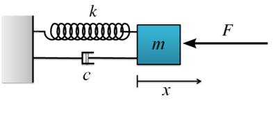
Figure 1. Spring-mass-damping system
Sound and vibration are essentially transmitted through different media. Just as vibration can produce sounds, sound waves can also cause vibrations of solid matter when it travels in the air. Because at the theoretical level, the two are interconnected, measurement sounds and vibrations are similar in nature.
You can think that both sound and vibration are oscillations. The simplest oscillation is a sine wave. Its expression is a formula that takes time as a parameter:
![]()
Among them, the angular frequency ω and the phase difference φ are fixed values. The unit of the angular frequency ω is radians per second (rad/sec), which is related to the frequency (Hz or sec-1), and the relationship between them is: ω = 2π?. The corner frequency is usually raised together with the phase difference φ. The phase difference φ is the waveform displacement corresponding to the starting time t0, which is expressed in degrees (°) or radians (rad).
Sound vibration measurement analysis
In practical applications, the measured voltage signal is a complex waveform that includes multiple frequency components. Acoustic vibration analysis generally includes confirming and checking these frequency components. In order to achieve this, you must transform the signal from the time domain to the frequency domain using mathematical methods such as Laplacian, zigzag, or Fourier transform. In particular, Fourier analysis, because it involves the decibel (dB) amplitude, and has a correlation with the phase difference φ (degrees or radians) of each frequency component in the signal.
IEPE sensor
Typical parameters for measuring sound vibrations are acceleration and sound pressure levels, respectively. These parameters are commonly measured by accelerometers (oscillations and vibrations) and loudspeakers (voices).
Many sensors that measure acceleration and pressure are based on the piezoelectric principle. Piezoelectric effect refers to the property of a ceramic or crystal crystal that generates a potential through compressive stress. These mechanical stresses are caused by acceleration, strain, or pressure. In the case of a loudspeaker, the pressure wave of the sound causes vibration of the diaphragm or the thin film and transfers the energy to the surrounding piezoelectric crystal. The accelerometer is equipped with vibration, which directly feedbacks vibration and vibration, and acts on the surrounding crystals. The magnitude of the voltage generated is proportional to the internal pressure of the crystal.
The IEPE is a special class of piezoelectric sensors in which an amplifier is mounted after the piezoelectric crystal. Due to the small voltage generated by the piezoelectric sensor, the generated electronic signal is easily affected by noise, so sensitive electronic devices must be used to amplify and restrict the signal and reduce the output impedance. Therefore, IEPE will install sensitive electronic devices as close as possible to the sensors to reduce noise interference and ensure the convenience of assembly. The conventional IEPE sensor uses an external DC power supply to provide the stimulus and adjust the output voltage based on the different amounts of power received by the piezoelectric crystal. IEPE uses only one or two wires for sensor excitation (current) and signal (voltage) output.
How to Perform Sound and Vibration Testing <br> Sound and Vibration Signal Conditioning Circuitry is very simple. Typical systems for measuring acceleration and sound pressure include the following elements:
sensor
Sensor excitation power
Suitable noise elimination grounding device
AC coupling to eliminate system DC offset
Use Instrumentation Amplifiers to Improve Sensor Signal Quality
Adding an anti-aliasing low-pass filter to the data acquisition system also reduces the new noise amplitude
Use synchronized sample-and-hold circuits to ensure signal simultaneity between channels
As mentioned earlier, sound and vibration tests are susceptible to noise. You can reduce the impact by properly grounding the system. You can also perform appropriate conditioning of the signal or ground the sensor to avoid ring grounding and floating nodes. If the sensor is grounded, the connection is different. If the sensor is floating, the inverting input of the signal conditioning system must be grounded.
The signal acquired by the sensor includes two parts of DC and AC, and the DC part may offset the AC part by zero. AC coupling can eliminate the DC offset in the system by connecting the signal capacitor. The AC-coupled sensor system eliminates the long-term DC drift of the sensor due to aging and temperature effects, thereby significantly increasing resolution and extending the system's available dynamic range.
In the precision measurement process, the sampling rate of the system must be at least twice the frequency of the signal being collected. To ensure that the frequency range is sampled correctly, install a low-pass filter in front of the ADC. This will ensure that you reduce the impact of high-frequency noise and also ensure that aliased signal components that are one-half the frequency of the sample rate do not affect the measurement results.
Sensor connection to measuring instrument
Example: The NI 9234 C Series module is specifically designed for accelerometer and loudspeaker measurements. (See Figure 2.) The NI 9234 can simultaneously acquire four analog input channels at a sampling rate of 51.2 kS/s. It also provides software switchable IEPE signal excitation, AC/DC coupling, and anti-alias filtering.
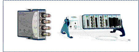
Figure 2. NI 9234 C Series Module Using the NI CompactDAQ Backplane
The module has four BNC connectors, each of which can be connected to an IEPE sensor (as shown in Figure 3). The central node of the connector, AI+ provides the DC excitation and the AC signal to be measured. The housing of the connector, AI-, provides the excitation return path and ground line of the AC signal to be measured.
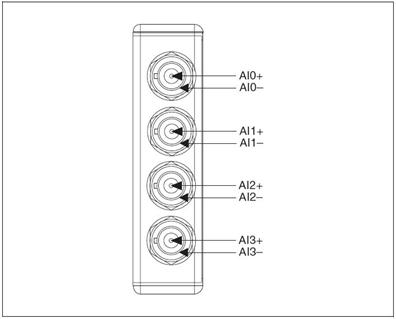
Figure 3. NI 9234 BNC Connector Assignment
The IEPE sensor requires a suitable cable and/or connector to be connected to the BNC input of the C Series module. The three-axis accelerometer has three outputs. One coordinate axis corresponds to one acquisition channel, and each requires an independent signal excitation source.
The NI 9234 can be connected either to a grounded IEPE sensor or to a floating IEPE sensor, but a floating connection must be used to prevent the introduction of ground noise. The typical IEPE sensor is electrically isolated from ground, so the NI 9234 is connected to the sensor even when the sensor is grounded.
Get Acquainted with Your Measurement System - NI LabVIEW
After you have properly configured your system hardware, you can use the LabVIEW graphical programming environment to capture and display data. (As shown in Figure 4)
In software use, you can use spectrum (frequency domain) analysis functions to convert the acquisition voltage to frequency waveforms. A simple example is the Fast Fourier Transform FFT function. You can also choose more advanced data software from National Instruments to provide you with more advanced data software, such as the NI Sound and Vibration Test Suite.
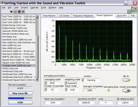
Figure 4. Power spectrum calculated using the NI Sound and Vibration Toolkit
Excerpt from: NI "General Measurement Guide"
Small Solar Panel,Small Solar Panels,4W Small Solar Panel,Small Solar Panel For Poly
Yangzhou Bright Solar Solutions Co., Ltd. , https://www.solarlights.pl