Coping with the challenges of eight-antenna LTE testing
At present, TD-LTE, FDD-LTE and LTE-Advanced (LTE-A) wireless technologies use several different multiple input multiple output (MIMO) technologies. In view of the increasing complexity of MIMO systems, the related test methods will also be more challenging. For example, currently deployed MIMO technology uses two antennas to improve channel performance. There are also some LTE communities that have taken the lead in adopting eight-antenna technology to achieve higher performance. These advanced technologies will make the choice of test methods even more critical.
To find the correct method, you must fully understand the antenna technology used in each version of LTE. For example, beams are a key feature of TD-LTE. Although it is an attractive transmission scheme in certain scenarios (such as open rural areas or hotspot coverage areas), it is not always the best method. Beamforming can improve the signal-to-noise ratio (SNR) of the received signal in the cell, thereby expanding coverage or improving the user experience in the cell edge area. It can also limit the range of the signal spatially, thereby minimizing interference. In areas with sufficient signal-to-noise ratio, beamforming does not increase the data rate.
By spatially multiplexing concurrent data streams, MIMO can improve data throughput under low-correlation and high signal-to-noise ratio channel conditions. To optimize the MIMO data rate, TD-LTE uses components containing eight antennas. In Figure 1, there are four antennas (shown in blue) that are physically polarized at the same angle, while the other four antennas (shown in green) form a physically orthogonal relationship with the previous four antennas .

Figure 1: A TD-LTE eNodeB antenna configuration can be used to optimize the MIMO data rate
By forming a beam directed to a specific user equipment (UE), these two sets of four antenna components can enhance the signal-to-noise ratio. Two orthogonally polarized beams can effectively mimic two antennas with low correlation, even if the actual spatial correlation is high. Therefore, this antenna configuration can expand the coverage and enable a wider range of high data rate transmission (Figure 2).
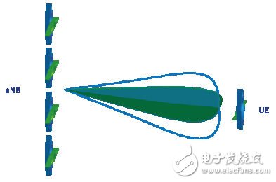
Figure 2: An 8 & TImes; 2 beam forming system forming orthogonal polarization beams
In addition to TD-LTE, eight-antenna technology can also be used for FDD-LTE. Network operators can use this antenna configuration to enhance uplink reception and solve the problem of link budget constraints for low-power user equipment. 3GPP's RAN1 working group is actively discussing the practical deployment of eight-antenna technology in LTE-A.
Fast Recovery Diode (FRD) is a kind of semiconductor diode with good switching characteristics and short reverse recovery time. It is mainly used in electronic circuits such as switching power supply, PWM pulse width modulator and inverter, as high frequency Rectifier Diode. Use for freewheeling diodes or damper diodes. The internal structure of the fast recovery diode is different from that of a normal PN junction diode. It belongs to a PIN junction diode, which adds a base region I between the P-type silicon material and the N-type silicon material to form a PIN silicon wafer. Since the base region is thin and the reverse recovery charge is small, the reverse recovery diode has a short reverse recovery time, a low forward voltage drop, and a high reverse breakdown voltage (withstand voltage value).
Fast Diode,Fast Recovery Rectifier Diode,Fast Recovery Diode,Fast Switching Diode
Dongguan Agertech Technology Co., Ltd. , https://www.agertechcomponents.com