8 lamp display design and simulation based on 8-key control
Project Requirements:
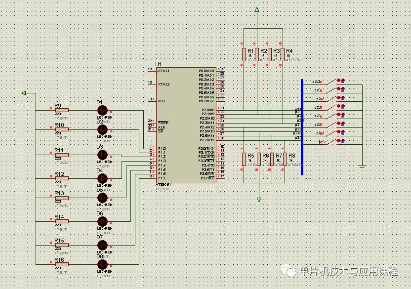
Use eight buttons (K0-K7) to control eight LEDs. Each button is responsible for turning on and off a corresponding LED. When K0 is pressed, D0 turns on; when K1 is pressed, D1 turns on, and this pattern continues up to K7 controlling D7.
Project Implementation:
Hardware Design:
In the PROTEUS software, the circuit is connected as shown in the figure below. The microcontroller is connected to the buttons and LEDs through appropriate I/O pins. The buttons are connected to the input ports of the microcontroller, while the LEDs are connected to the output ports with current-limiting resistors to prevent damage.
Software Design:
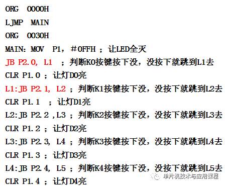
The program is written and edited in Keil software. After writing the code, it is compiled to generate a .HEX file, which is then used to program the microcontroller. The code should handle the input from the buttons and control the corresponding LEDs accordingly.
Simulation Steps:
1. Assign the generated .HEX file to the microcontroller in the PROTEUS simulation environment.
2. Run the simulation and observe the behavior of the LEDs when each button is pressed.
Expanding Task:
Task Requirements:
If you want to make a single LED blink for 1 second on and 1 second off, repeating this cycle 10 times, and then turn on continuously, how would you approach this task?
Task Implementation:
1. Draw the hardware diagram to connect the microcontroller, buttons, and LEDs properly.
2. Create a flowchart that outlines the logic of the program, including the blinking sequence and the timing functions.
3. Write the corresponding C or assembly code to implement the blinking functionality using delay functions.
4. Debug the program and simulate it in PROTEUS to ensure the LED behaves as expected.
Explosion Proof Motor,Explosion Proof Servo Motor,Exproof Motors,Explosion Proof Ac Motor
Yizheng Beide Material Co., Ltd. , https://www.beidevendor.com