Working principle of hydraulic press
Its principle is to make use of Pascal's law to make use of hydraulic pressure transmission machinery, there are many types. Of course, the uses are also diverse according to needs. For example, according to the type of liquid that transmits pressure, there are two categories: hydraulic press and hydraulic press.
1. The hydraulic pump is the driving force of the hydraulic system. The work of the hydraulic machine is to make the hydraulic oil enter the cylinder/piston through the hydraulic pipeline by the driving force of the pump.
2. There are several sets of matching seals in the cylinder/piston. The one-step seals are not compatible, but they all act as a seal to persuade the hydraulic oil to not flow out.
3. At the end of the work, the hydraulic oil is circulated in the oil tank through the one-way valve to make the cylinder/piston circulate to do work.
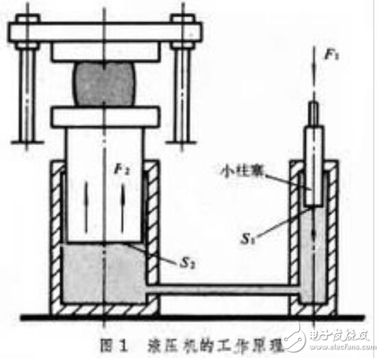
The areas of the large and small plungers are S2 and S1 respectively, and the forces on the plungers are F2 and F1 respectively. According to Pascal's principle, the pressure of a closed liquid is equal everywhere, that is, F2/S2=F1/S1=p; F2=F1 (S2/S1). It represents the gain effect of hydraulic pressure. Like mechanical gain, the force increases, but the work does not gain. Therefore, the movement distance of the large plunger is S1/S2 times the movement distance of the small plunger.
The basic principle is that the oil pump delivers hydraulic oil to the integrated cartridge valve block, and distributes the hydraulic oil to the upper cavity or lower cavity of the cylinder through various one-way valves and overflow valves, and moves the cylinder under the action of high pressure oil. A hydraulic press is a device that uses liquid to transmit pressure. When the liquid transfers pressure in a closed container, it follows Pascal's law. The hydraulic transmission system of a four-column hydraulic press consists of a power mechanism, a control mechanism, an executive mechanism, an auxiliary mechanism and a working medium. The power mechanism usually uses an oil pump as the power mechanism, which is generally a product oil pump. In order to meet the requirements of the motion speed of the actuator, one oil pump or multiple oil pumps are selected. Gear pumps for low pressure (oil pressure less than 2.5MP); vane pumps for medium pressure (oil pressure less than 6.3MP); plunger pumps for high pressure (oil pressure less than 32.0MP). Pressure processing and forming of various plastic materials, such as extrusion, bending, deep drawing of stainless steel plates and cold forming of metal parts. It can also be used for pressing powder products, grinding wheels, bakelite, and resin thermosetting products.
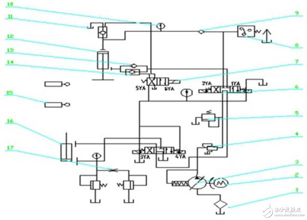
When the hydraulic press is working, the electro-hydraulic reversing valve 6 is energized by the pump 3 and the oil pressure will enter the right position of the electro-hydraulic reversing valve 6 through the sequence valve 4, and then into the upper cavity of the upper cylinder 12 through the one-way valve 9, and then through the solenoid Valve 7 replenishes oil into the upper chamber of the oil cylinder, and returns oil from the lower chamber of the upper cylinder, through the one-way sequence valve back pressure valve 13 and the hydraulic control check valve 14, and flows back to the oil tank through the electro-hydraulic reversing valve 7; the upper cylinder of the hydraulic machine Under the action of its own weight, the rapid downward movement is accelerated, so that the upper cavity of the upper cylinder instantly forms a vacuum. The oil in the replenishment tank will be sucked into the upper cavity of the upper cylinder through the hydraulic control check valve to eliminate the vacuum and maintain the rapid lowering of the upper cylinder. shift.
When the upper cylinder of the hydraulic press drives the upper mold and the lower mold to close, the oil continues to enter the upper cavity of the upper cylinder, the pressure in the upper cavity of the cylinder rises, and the hydraulic control check valve at the replenishment tank is closed, cutting off the oil supply to the replenishment tank. The downward speed of the upper cylinder 12 begins to slow down, and the pressure in the upper chamber of the cylinder continues to rise. When the setting value of the pressure relay 10 is exceeded, a signal will be sent to control the electro-hydraulic directional valve 6 to switch to the neutral position to cut off the upper chamber of the cylinder 12 Supply oil, the upper cylinder of the hydraulic press stops the motion system, and starts to maintain pressure for about 40s; after completion, the left position of the hydraulic electro-hydraulic directional valve 6 is connected, and the pressure oil from the pump 3 passes through the sequence valve 4 and passes through the electro-hydraulic directional valve 6. In the left position, through the hydraulic control check valve 14 and the back pressure valve 13, enter the lower cavity of the upper cylinder 12. While pushing the cylinder upward, the solenoid valve 7 is switched to the left position, and the oil tank replenishes the oil to accelerate the return stroke; the upper cavity of the cylinder 12 of the hydraulic machine The oil return flows back to the charge tank 11 through the hydraulically controlled check valve, and finally the upper cylinder can quickly return to its original position.
When the middle position of the electro-hydraulic directional valve 6 and the right position of the electro-hydraulic directional valve are connected, the pressure oil discharged by the pump 3 enters the lower cavity of the lower cylinder 16 through the left position of the electro-hydraulic directional valve of the hydraulic machine, and the oil is returned from The upper cavity of the lower cylinder 16 flows into the oil return tank through the left position of the electro-hydraulic reversing valve, and the lower cylinder ejects the workpiece upward; after the workpiece is taken out, the right position of the reversing valve of the hydraulic press starts to work, and the pressure oil enters the upper cavity of the lower cylinder 16. The return oil from the lower chamber of the lower cylinder flows into the return tank through the right position of the valve, and the lower cylinder moves downward to return to its original position; the valve 13 can prevent the oil in the upper chamber of the upper cylinder 12 from flowing back when the pressure is maintained. The stroke switch 15 is used to control the upper chamber. , The limit position of the lower cylinder, at this time the pressure gauge respectively shows the pressure value of the upper and lower cylinders of the hydraulic press and the entire system.
Recommended reading:
The principle of hydraulic press _ the role of hydraulic press
Classification of hydraulic press_safety operation rules of hydraulic press
Pressure calculation method of hydraulic press_what is the reason for the weakness of hydraulic press
What is a hydraulic press used for_advantages and disadvantages of a hydraulic press
Dongguan Guancheng Precision Plastic Manufacturing Co., Ltd. , https://www.dpowerchargers.com