The role, classification and drive circuit design of digital tube drive circuit
The role of the digital tube driver circuit:
The function of the digital tube driving circuit is mainly to control the LED digital tube (light emitting diode) circuit by using a single chip microcomputer to realize the dynamic display effect of the digital output of the digital tube LED screen.
Classification of digital tubes:
(1) Classified according to the number of digital pipe segments
The digital tube is a semiconductor light emitting device whose basic unit is a light emitting diode. It is divided into seven segments of digital tubes and eight segments of digital tubes according to the number of segments. The eight-segment digital tube has one more LED unit than the seven-segment digital tube (that is, one more decimal point display);
(2) According to the digital tube digital display classification
According to how many "8" can be displayed, it can be divided into 1, 2, 4, etc. digital tubes;
(3) Classification according to digital tube connection
According to the connection mode of the LED unit, it is divided into a common anode digital tube and a common cathode digital tube.
Gongyang Digital Tube and Gongyin Digital Tube:
Among them, the common digital tube refers to a digital tube that connects the anodes of all the light emitting diodes together to form a common anode (COM). The common anode digital tube should connect the common pole COM to +5V when applied. When the cathode of a field LED is low, the corresponding field will light up. When the cathode of a field is high, the corresponding field is not lit.
The common cathode digital tube refers to a digital tube that connects the cathodes of all the light emitting diodes together to form a common cathode (COM). When the common cathode digital tube is applied, the common pole COM should be connected to the ground line GND. When the anode of a field LED is high level, the corresponding field will be lit. When the anode of a field is low, the corresponding field is not lit.
Example of common anode digital tube drive circuit:
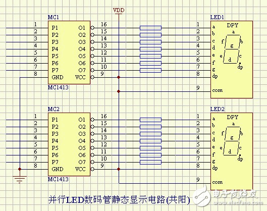
Parallel LED digital tube static display circuit (common yang)
Common Yin digital tube driver circuit example:
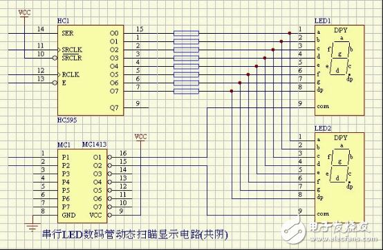
Serial LED digital tube dynamic scanning display circuit (total)
More common digital tube and common cathode digital tube driver circuit, please click the following link to browse:
The following provides a digital tube driving circuit design, which can realize the digital 0~9 control output of the LED digital tube.
working principle:
As shown in Figure 1, the circuit consists of a NAND gate 74LS00 and a digital tube driver chip 74LS247. The 10 buttons form the input circuit. After the NAND gate circuit is encoded, the digital tube driver chip is input, and the digital tube is driven to display the corresponding button number.
When designing the key encoding circuit, first write out the truth table, and the truth table can write the following formula:
A={I1 ·I3 ·I5 ·I7 · I9 } (in the braces, each factor is inverted and together are inverted) = I1+I3 +I5 +I7 +I9
B={I3 ·I4 ·I6 · I7} (in the braces, each factor is inverted, and then together are reversed) = I3+I4+I6+I7
C={I4 ·I5 ·I6 · I7} (in the braces, each factor is inverted, and then together are negated) = I4 +I5 +I6+I7
D={I8 · I9 } (in the braces, each factor is inverted, and then together are reversed) = I8+I9
In order to make the power supply voltage not exceed the voltage range of the digital tube, the power supply is connected in series with four diodes and then added to the digital tube. This saves components.

Circuit schematic 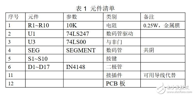
Component list
Antenk MICRO USB :Micro USB is a miniaturized version of the Universal Serial Bus (USB) interface developed for connecting compact and mobile devices such as smartphones, MP3 players, GPS devices, photo printers and digital cameras.
Micro USB connectors exist or have existed in three forms: micro A, micro B and micro USB 3. USB 3 micro is much like micro B, but with an additional pin group on the side for twice the wires, enabling USB 3's greater speed. Like standard USB, the micro versions are plug-and-play and hot-swappable.
Micro Usb2.0 B Female,Micro Usb SMT Dip,Usb SMT Dip with Flange,Micro Usb B Female SMT Dip
ShenZhen Antenk Electronics Co,Ltd , https://www.atkconnectors.com