Research on Perceptual System of Wearable Lower Limb Booster
1 Introduction
This article refers to the address: http://
The wearable lower limb assisting robot is a kind of auxiliary rehabilitation robot, and is a power assisting device that helps people to expand the lower limbs' movement ability. The basic principle is based on the human body motion behavior awareness information, and is installed on the leg joints ( The servo motor at the hip joint and the knee joint drives the joint motion, and the joint movement and the value of the speed change to achieve coordinated movement with the human leg and provide assistance to reduce the exercise intensity of the person under heavy load or long walking. The treatment and orthopedics of those who have abnormal sports behaviors form a harmonious and perfect whole with the human body. At present, there are about 10 laboratories in the world engaged in the research of wearable human-powered robots. Among them, Japan and the United States are at the forefront, and no relevant reports have been reported in China. In 2002, Tsukuba University of Japan developed a hybrid hybrid assis-tive limb (HAL). The mechanical exoskeleton was tied to the sides of the human leg, using an EMG sensor attached to the skin of the leg. The muscle current is detected and the electric motor is controlled to drive the mechanical exoskeleton movement to assist the movement of the leg. The University of California, Berkeley, Robotics and Ergonomics Laboratory developed the US Army "Berkeley lower extremity exoskeleton" (BLE-EX), consisting of a backpack-style outer frame, metal legs and corresponding hydraulic drive equipment. Similar to the humanoid structure, the backpack-type outer frame enables the operator to carry a certain load, and its effective force is transmitted directly to the ground through the exoskeleton without passing through the wearer. The lower extremity exoskeleton can carry an external load and its own weight (including the weight of the operator) to travel long distances on rough roads, enabling soldiers with fully armed forces to increase their weight-bearing capacity and speed their march. However, the above devices have the common disadvantage that the myoelectric sensor is based on the weak current signal transmitted by the skin surface during muscle activity or the softness and hardness of the muscle to infer the behavioral awareness of the human body, resulting in most of the sensors used directly with the human skin. Contact and paste on the skin requires special fixing devices, which directly leads to inconvenience in wearing; the sweat secreted by the human body and the quality of the sensor installation will affect the stability and accuracy of the acquired information, and the amount of information is large and complicated. It is susceptible to interference, making control more difficult. Therefore, this paper designs a new type of wearable lower limb assisted robot sensing system, which is used to obtain the contact force between the human lower limb and the robot exoskeleton. The force information and joint angle information are used to control the robot exoskeleton to achieve the human body. The power of lower limb movement.
2 power robot system
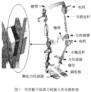
The wearable lower limb assisting robot is mainly composed of three parts: mechanical, sensing and control. The robot's outer skeleton contains 12 degrees of freedom, each leg has 6 degrees of freedom, the hip joint contains 3 degrees of freedom, and the knee, ankle, and sole each contain one degree of freedom. This design requirement not only conforms to the previous anthropomorphic robot walking. The design requirements of the mechanism, and the design requirements that are in harmony with the movement of the human leg and do not produce motion interference, as shown in Figure 1.
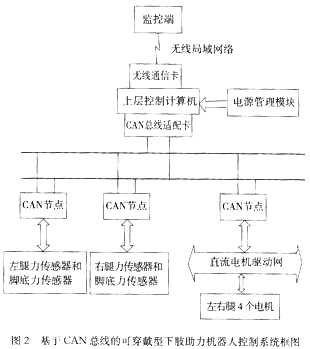
The executive part mainly refers to the DC servo motor. The system requires four, which are fixed on the hip joints and knee joints of the two legs. The wearable lower limb assisted robot control system mainly adopts PC104 embedded control system board and PC104CAN card. The control structure of the whole system is shown in Fig. 2.
3 robot perception module
3.1 Human-machine system contact information
The wearable lower limb assisting robot mainly uses the information of the lower limb movement of the human body to provide assistance. The motion information mainly includes the contact force signal of the leg of the human body and the exoskeleton robot, the signal of the sole force, and the angle signal of the knee joint and the ankle joint. In order to obtain these motion information, a multi-sensor sensing system based on CAN bus is designed to solve the problems of single sensor and poor real-time performance of traditional sensor communication methods (mainly RS-232 and RS-485). The system consists of a motor code wheel, two two-dimensional force sensors mounted on the leg, and six one-dimensional force sensors mounted on the sole of the foot. The leg force sensor is fixed on the upper part of the knee and the ankle joint of the human leg to measure the contact force between the human body and the exoskeleton; the sole force sensor is mounted on the toe and the heel for measuring the ground reaction force; the motor code wheel is used for measurement The angle of rotation of the hip and knee joints is shown in Figure 1.
3.2 System Design
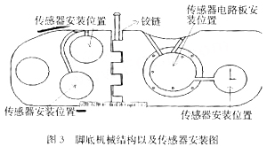
The two-dimensional force sensor of the leg is a sensor for measuring the contact force between the exoskeleton of the robot and the human body, and the accuracy and stability of the measurement have important significance for the control of the assisted robot. The leg force sensor is mainly composed of two two-dimensional force sensors for measuring the contact force between the human body's large and small legs and the robot's exoskeleton. The contact force includes the force along the human leg (X direction) and the vertical leg. Force (Y direction). In the control of the lower limb assisted robot, in addition to knowing the force of the human leg and the robot, it is also necessary to know the force of the human sole to the robot, and the foot force sensor is to measure the reaction of the ground to the human-machine system. . The point of focus of the human body on the ground can be represented by three support points, which are located at the root of the first metatarsal and the root of the fifth metatarsal and the heel, respectively, and the human body supports the body by the arch generated between the three points. The weight of the body is transmitted to the ground through these three points. In order to accurately obtain the force information of the sole of the foot during walking, the installation position of the sole force sensor is set at these three points. Each foot needs to install three one-dimensional force sensors, and a total of six one-dimensional force sensors are required. The specific installation position See Figure 3. Due to the limitation of the mechanical part of the sole, the sensor elastomer is relatively small in volume, and its body mechanical size is φ40 mm (diameter) × 8 mm (thickness), and the range is 1000 N.
3.3 Sensor design
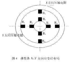
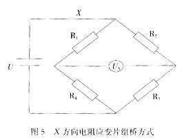
Elastomer design is the key to multidimensional sensor design. Based on the simulation analysis of the static and dynamic characteristics of the sensor elastomer using finite element analysis method, an elastomer structure based on E-type diaphragm is designed. The sensor has simple structure, high sensitivity and inter-dimensional coupling. Small, easy to calibrate features. The whole elastic body is mainly composed of three parts: elastic diaphragm, strain gauge and force transfer body. The elastic body is composed of two E-type diaphragms to measure the strain in both directions of X and Y. The elastic diaphragm has a circular structure with diameters and thicknesses of φ15 mm and 2 mm, respectively, and the thickness direction is consistent with the measurement direction. The sensitive component is a foil-type strain gauge, and the strain gauge is attached to the E-type diaphragm. The output of the sensor is the stress of the E-type diaphragm. There are many ways to measure the stress. In this study, a foil-type strain gauge is used, and the strain gauge is attached to the E-type diaphragm to measure the stress on the elastomer. The position of the strain gauge patch is shown in Figure 4. The X and Y strain gauges are mounted on the lower end of the E-type diaphragm. The four strain gauge resistors form a Wheatstone full-bridge circuit (as shown in Figure 5) to achieve the output signal. Automatic decoupling. When the force acts on the sensor, the sensitive resistance of each direction is different due to the difference in force and direction, and the relationship between force and strain is obtained. Taking the X direction as an example, the circular flat diaphragm of the sensitive elastic portion of the E-type diaphragm belongs to a thin plate structure. Under the action of the X-direction force, the boundary condition is relatively simple, and the outer circumference can be equivalently fixed, and the concentrated stress acts on the hard center. Round sheet. According to the thin plate theory, the radial stress εr and the tangential stress εθ of the diaphragm with a hard center at the radius r are
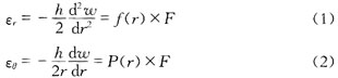
Where: ω, h are the normal displacement and thickness of the circular diaphragm; F is the equivalent concentrated force of the applied force; f(r), P(r) is a function only related to r.
It can be seen from the above equation that when the radius r is constant, that is, when the varistor is fixed, the strain ε on the surface of the circular diaphragm is
ε=kFF (3)
Where kF is the strain coefficient constant.
Due to the use of an equal arm bridge, ie R1=R2=R3=R4, there is
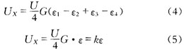
Where: ε1, ε2, ε3, ε4 are the strains of four sensitive resistors R1, R2, R3, and R4, respectively; ε is the total strain of the circular diaphragm; G, k is a constant; UX is the bridge output voltage.
In combination (4), (5), the output voltage signal of the bridge is proportional to the force signal of the sensor, and the output signal voltage is measured to obtain the force signal of the target to be measured.
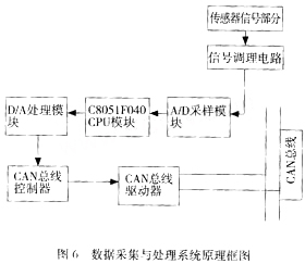
The sensor hardware circuit adopts embedded on-chip system, which consists of two parts: digital circuit and analog circuit. The analog circuit consists of signal zeroing circuit, operational amplifier circuit and analog filter circuit. The digital circuit part mainly includes A/D sampling module and digital calculation. Module, CAN bus controller, CAN bus driver and necessary peripheral circuit modules. Figure 6 is a block diagram of the hardware circuit of the data acquisition and processing system of the power-assisted robot force transmission system.
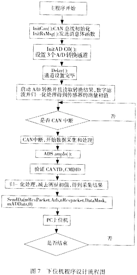
The software design is divided into the software design of the lower computer (microprocessor) and the software design of the upper computer (PC). Each sensor is interconnected as a node through the CAN bus. When receiving the command from the host computer, the command is first judged and the corresponding data is processed according to different commands. The host computer (PC) mainly includes commands such as clearing point, force information (digital quantity), returning force information, query power information, and shielding alarm. The software design of the lower computer is mainly composed of three parts: data acquisition program (A/D conversion), data processing program and CAN bus communication program. Before starting the CAN interrupt, perform data acquisition in the main program to get the initial value of the sensor system, including 3 A/D conversion channels; delay, complete channel initialization; data acquisition is done in the CAN interrupt program. Each interruption completes the acquisition of a set of three-dimensional force information data and the corresponding A/D conversion; simultaneously reads the conversion result and digitally processes the conversion result, and the digital processing mainly consists of two parts: digital filtering and force information decoupling. The digital filtering mainly uses the window moving method and the data average method; after the data is decoupled, the data is sent to the CAN bus through the SendData() function, and the upper computer recognizes the data of the lower computer through the ID number. The specific process is shown in the figure. 7.
4 sensor calibration experiment
The complexity of the structure of the E-type diaphragm makes the consistency of the product characteristics more difficult than that of the one-dimensional sensor. It is difficult to guarantee the absolute ideal condition by the patching process of the strain gauge. These factors determine the actual static characteristics of the sensor and the theoretical calculation value. There is a certain error, so the static characteristics of the sensor are generally obtained by the calibration experiment method, and the calibration accuracy will directly affect the measurement accuracy when the sensor is used. The so-called sensor calibration is to establish the quantitative relationship between the three output values ​​of the sensor and the three-dimensional force acting on the origin of the sensor coordinate system. The calibration experiment process includes two parts: static calibration and real-time measurement verification. In order to reduce the influence of random errors, a least squares calibration method with a certain redundant force vector is adopted. Let F be the loading force matrix, V be the output matrix of the sensor (digital quantity), C be the calibration matrix, and E be the error matrix.
F=CV+E (6)
Where: F, V is a known amount; E can be set. Thus, the solution of the calibration matrix can be transformed into solving the calibration matrix C, so that equation (6) is optimal in the sense of least squares. In the calibration process of the miniature finger force sensor, the relationship between the load applied to the sensor in the X, Y direction and the sensitive bridge is measured. The corresponding relationship between the measured value (digital quantity) and the added weight value is shown in Fig. 8. Shown (XLable represents the load applied to the sensor calibration and Ylable represents the digital output of the sensor).
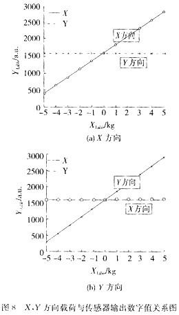
It can be seen from Fig. 8 that when the sensor X is forced in the direction of the force, the mapping relationship between the received load and the sensor-sensitive bridge output can be basically considered to be linear, and the maximum coupling in the Y direction is not more than 2.5%. The two sets of static calibration matrices of the sensor are obtained by least squares method, so that the class I error of the sensor can be calculated to be 2%, and the class II error is 2.5%. Ligang C1, C2 two sets of calibration matrix for real-time measurement of the sensor test, the results show that the maximum error of class I does not exceed 2%, class II error does not exceed 2.5%. The static calibration matrix obtained by the calibration system is close to the theoretical design value, indicating that the calibration system and the calibration scheme are feasible.
5 Conclusion
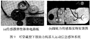
Aiming at a new type of human-assisted rehabilitation robot, this paper designs a set of lower limb motion information sensing system based on CAN bus, as shown in Figure 9. After analyzing the control information required by the wearable power-assisted robot, the type, quantity and installation position of the sensor can be determined; the elastic body design of the leg and foot force sensor, the measuring circuit and the upper and lower machine software are mainly introduced; the calibration experiment of the sensor is performed. The data is analyzed and the general performance indicators of the sensor are given. The results show that the design theory and design process in this study are correct and can basically meet the needs of the wearable lower limb assisted robot control system. The future work is mainly focused on the following points: (1) Continue to improve the elastomer structure of the sensor, further reduce the volume of the sensor elastomer and accurately determine the patch position of the strain gauge based on the performance of the sensor; 2 Improve the measurement circuit of the sensor Design, increase the filter circuit, improve the amplifier circuit; 3 improve the sensor calibration system to minimize the calibration error.
LED module introduction: LED Display Module is one of the main components of the finished Led Display! It mainly consists of LED lamp, PCB board, driver IC, resistor, capacitor and plastic kit!
Classification of Led Display Module
From the light color
LED display module is divided by color:
I. monochromatic modules, such as single red, single green, single blue, single yellow and single white modules
2. Two color modules, such as red and green, red and blue.
3. full color module is mainly a product with red, green and blue primary colors on one LED module

According to the purpose of LED display
LED display module is divided into indoor, semi outdoor and outdoor, grid screen, strip screen, glass screen, etc. according to the different use space.
From the use of lamp beads
According to different LED packaging devices, LED display module can be divided into: LED display module of direct light, LED display module of indoor lattice, LED display module of surface mount.
Divide by pixel spacing
According to the LED pixel spacing, generally used more is: p1.25, p1.875, p1.56, P2, P3, P4, P5 and so on.
LED display function
1. Play the role of commodity publicity and attracting customers.
2. Play the role of store decoration and improve the level of enterprises.
3. Play the role of lighting and innovation.
4. Play the role of popularizing knowledge. (it can be used to play small information of enterprise products and knowledge of relevant industries)
5. Play the role of bulletin board. (promotion, recruitment information release)
6. Act as a foil to the atmosphere. Through the display screen, you can play the welcome words of superior leaders and various VIPs to visit and guide, and the celebration words of various major festivals.
7. It plays a warning role and is often used for road traffic LED navigation indication, etc.
It is undeniable that the ultimate purpose of establishing billboards is to publicize commodity information, attract target customers and make the most profit as much as possible. Led billboard is to achieve this goal to become the first choice of enterprise publicity.
LED Display Module
Led Display Module,Single Led Display Module,Soft Led Display Module,Flexible Led Display Module
Shenzhen Vision Display Technology Co,.LTD , https://www.ledvdi.com