Reduce noise and power consumption in car audio systems with SigmaDSP
Nowadays, as multimedia technology is gradually adopted by in-vehicle electronic devices, digital signal processors (DSPs) have also become more and more widely used to digitize audio signals. For example, in-vehicle multimedia systems replace traditional car radios and CD systems, and DSPs such as ADI's ADAU1401 SigmaDSPTM are used in this multimedia system to achieve superior sound and high flexibility, providing passengers with a rich multimedia experience. In addition, these DSPs provide a useful tool for reducing system noise and power consumption, which is useful for system engineers who are concerned with noise and power issues. This article introduces this new approach, using SigmaDSP processors and SigmaStudioTM graphics development tools to reduce noise and power consumption in car audio systems.
This article refers to the address: http://
The ADAU1401 is a complete single-chip audio system that includes a fully programmable 28/56-bit audio DSP, analog-to-digital converter (ADC), digital-to-analog converter (DAC), and microcontroller-like control interface. Signal processing includes equalization, bass boost, multi-band dynamic processing, delay compensation, speaker compensation, and stereo sound field widening. This processing technology is comparable to the effects of high-end studio equipment, and can compensate for the distortion caused by the practical limitations of speakers, amplifiers and listening environments, thus significantly improving the sound quality.
With the easy-to-use SigmaStudio development tools, users can graphically configure signal processing flows using different functional blocks, such as biquad filters, dynamic processors, level control, and GPIO interface control.
Noise floor
Unlike portable devices, car audio systems are equipped with high-power amplifiers, each capable of delivering up to 40 W-50 W, with at least four speakers per car. Due to the high power, the noise floor is easily amplified, making the human ear feel in a quiet environment. For example, assuming a speaker sensitivity of approximately 90 dB/W, a 1 mV rms noise in a 4 Ω speaker can produce a sound pressure level (SPL) of approximately 24 dB, which can be felt in a quiet environment. There are many possible noise sources. As shown in Figure 1, the main noise sources include power supply noise (VG), filter/buffer noise (VF), and noise VE caused by improper power supply grounding. VO is the audio signal from the processor and VIN is the audio input signal from the speaker power amplifier.
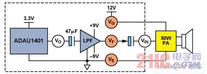
Figure 1. Example of a noise source for a car audio system
Burst during power switch: Car audio power amplifiers typically operate from a single 12 V supply, while DSPs require a low voltage supply (such as 3.3 V) and the filter/buffer may be powered from dual supplies (eg ±9 V). Coupling capacitors must be used to provide signal isolation between circuits that operate at different supply voltages. During power on/off, the capacitor is charged/discharged at an extremely fast rate, and the resulting voltage jump propagates along the signal chain, eventually causing the speaker to pop. Figure 2 shows this process.
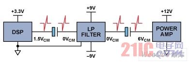
Figure 2. The principle of the speaker producing a pop
While knowing the source of noise and popping, and trying to use good circuit design and place-and-route technology, as well as selecting better devices with lower noise to reduce noise at the source, there are still many uncertainties that can occur during the design process. . Designers of automotive multimedia systems must deal with many complex issues and must have a high level of analog/mixed-signal design skills. Even so, the performance of the prototype product may still be inconsistent with the original expectations. For example, a noise level of 1 mV rms poses a huge challenge. As for popping, existing solutions use MCUs to control the order of operation of the power amplifiers during power switching, but when the MCU is far from the power amplifier, place and route and electromagnetic interference (EMI) pose potential problems.
Power consumption
With the increasing number of in-vehicle electronic devices, power consumption issues have become increasingly serious. For example, if the audible current of the audio power amplifier reaches 200 mA, the static power consumption is as high as 2.4 W with a 12 V supply. If there is a way to detect that there is no input signal or the signal is small enough to turn off the power amplifier, then you can save a lot of power when it is turned on but does not require the speaker to make a sound.
Minimize noise and power consumption in car audio systems
Using SigmaDSP technology, you can provide a way to reduce system noise and power consumption without increasing hardware costs. Figure 3 is a block diagram of a 4-speaker car audio system in which the ADAU1401 SigmaDSP processor is used as an audio post processor. In addition to sampling, conversion, digital processing of audio signals, and generation of additional speaker channels, the SigmaDSP processor also features general purpose input/output (GPIO) pins for external control. The microcontroller (MCU) communicates with the SigmaDSP processor via an I2C interface that drives a low-pass filter/buffer stage using the precision op amp ADA4075-2.
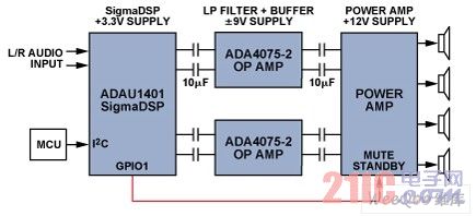
Figure 3. Four-speaker car audio system
The red signal line between the SigmaDSP processor and the power amplifier controls the mute/standby pin of the power amplifier. In the normal default operating mode, the open-collector GPIO1 pin is set high by a 10 kΩ pull-up resistor (not shown). The ADAU1401 has a rms signal detection function to determine if an input signal is present. When there is no input signal, GPIO1 goes low and the power amplifier is placed in the mute/standby mode, so the speaker has no noise output and the standby power consumption of the amplifier is also low. When an input signal above a predetermined threshold (eg –45 dB) is detected, GPIO1 goes high and the power amplifier operates normally. At this time, although the noise floor still exists, it is shielded by the high signal-to-noise ratio (SNR) of the signal, making it difficult for the human ear to perceive.
During the power switch, the SigmaDSP processor (rather than the MCU) directly controls the power amplifier's mute/standby by responding to the MCU's commands. For example, during power-on, the control signal from the MCU sets the GPIO1 of the SigmaDSP processor through the I2C interface to keep it low (mute) until the predetermined capacitor charging process is complete, then the MCU sets GPIO1 high. , thereby eliminating the popping caused by the startup transient. When the power is turned off, the GPIO immediately goes low, which puts the power amplifier in a mute/standby state, thereby eliminating the popping sound generated when the power is turned off. The reason for placing the power amplifier under the direct control of the SigmaDSP processor rather than the MCU is that the SigmaDSP processor is typically closer to the power amplifier, so placement and routing and EMI control are also easier to implement.
As described above, the rms level of the input signal can be measured using the SigmaStudio software algorithm. Using the SigmaStudio graphical development tool, it is easy to set up the rms detection module and use it to control the GPIO state, as shown in the example in Figure 4.
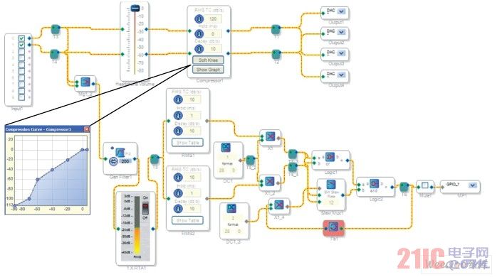
Figure 4. SigmaStudio rms detection, GPIO control, and compressor circuit diagram
The root mean square detection function is implemented by using a root mean square algorithm unit and a logic unit. The signal threshold must have a hysteresis function to eliminate chattering caused by small changes in the mute function response. For example, the RMS1 threshold is set to –45 dB and the RMS2 threshold is set to –69 dB. GPIO1 is high when the input signal is above –45 dB. GPIO1 is low when the input signal is below –69 dB. When the input signal is between these two thresholds, the GPIO1 output signal remains in the previous state (see Figure 5).
Figure 4 also shows the compressor function to further reduce output noise. For example, when the input signal is below –75 dB, the output signal from the speaker system will attenuate to –100 dB, which also reduces the system noise floor.
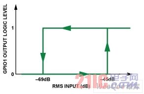
Figure 5. RMS threshold settings and the relationship between input and output
to sum up
Noise and power consumption are huge challenges in the design of car audio systems. ADI's SigmaDSP processor has been widely used in digital audio post-processing of car audio systems, and its use of rms detection and GPIO control to significantly reduce noise and power consumption can further play a greater role. SigmaStudio graphical development tools support graphically setting up various functions without the need to write code, making design work easier. In addition, since the power amplifier module is usually closer to the SigmaDSP processor than the MCU, using the SigmaDSP processor to control the mute function simplifies the place and route work and improves EMI immunity.
Yageo Resistor,Dip Resistor,Surface Mount Resistor,Surface Mount Resistor
JINGGANGSHAN MEICHENG ELECTRONIC TRADING CO.,LTD , https://www.meicheng-tra.com