Overall solution for automotive system design

Summary
This paper presents a vehicle system design methodology that uses standardized, hierarchical functions as a single level to describe electrical, electronic, and software content. The execution level of the specific domain is then generated in a synthesis process and evaluated using the appropriate metrics. The focus is on rapid iterative optimization and evaluation and verification of cross-domain architectures.
Function-based system engineering
Introducing and developing a system architecture in a functional way is usually based on a domain-specific language derived from UML (Unified Modeling Language) such as EAST-ADL or SysML. At the same time, the technical content (components) of the system to be developed is introduced in various forms and abstraction levels (eg, functions, activities, sequences, and/or state diagrams) and then appropriately mapped for execution.
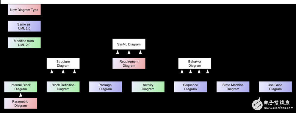
SysML graph type (taxonomy), from Wikipedia.
Using this method requires a lot of work, is not suitable for architectural evaluation, and is more suitable for detailed archiving. In fact, in order to be able to make meaningful technical and financial assessments of the overall system architecture, each individual level must be clarified in great detail until a sufficient level of detail is reached. In subsequent mappings, the workload increases by the square of the level of detail: for example, the number of artifacts in a single hierarchy.
If the corresponding metrics are not sufficiently agile, it is not possible to evaluate changes in functional allocations in a timely manner, and it is not possible to provide truly meaningful results for each individual choice to be evaluated, such as a software component of a specific control unit.
Overall, this has greatly affected the study of architecture. In some cases it may take more time to provide the necessary data and calculate the desired indicator than the original project planned!
Functional model
The other approach presented in this paper uses a standardized, hierarchical functional model at a single level to describe the technical content of the system architecture. In this paper, standardized functional models refer to individual functions that can be separated from their final implementation as hardware, drivers, and software components. Models are no longer distributed at multiple (and in some cases redundant) levels, but instead a single specific domain description can be combined with a single functional abstraction, eliminating the lengthy mapping process. Communication between individual functions is achieved by signals that can be standardized (becomes software, electrical or bus signals). All artifacts can be related to a set of rules from a detailed option/variant model. Component models of hardware, software, and electronic & network communications can thus be integrated and use Design Rule Check (DRC) to simultaneously examine and validate their semantic dependencies.
In this way, the technology of the downstream execution domain (hardware, software, network, and electrical), the variant-driven content can be captured early in the functional abstraction hierarchy, and verified in all variants.
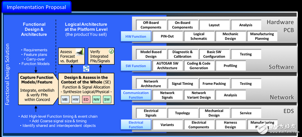
Specific domain processes and upstream functional architecture design.
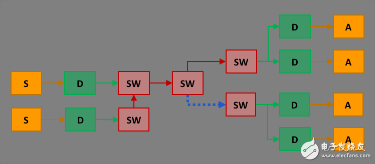
feature design.
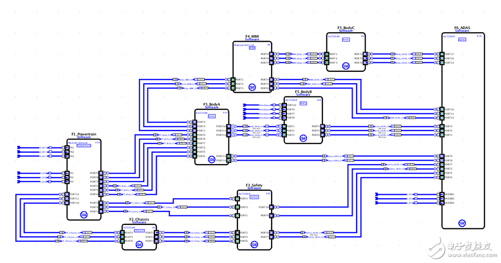
To illustrate this approach, Figure 3 shows a number of functional blocks. Software functions (SW), driver components (D), sensors (S) and actuators (A) are described and displayed at a single level of abstraction. The signals between functions are displayed according to the color they need to perform: red (SW), green (electronic signal on the PCB), orange (electronic signal on the harness), and blue (signal on the network).
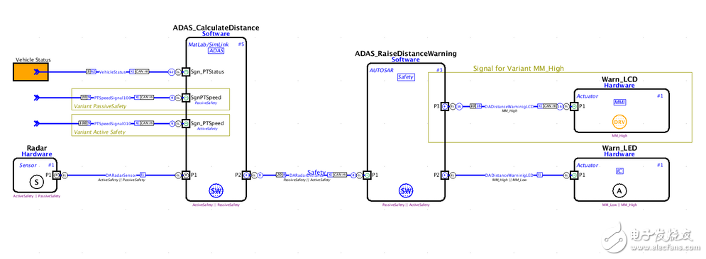
A functional diagram that identifies various functions, option assignments, and external function blocks or signal references.
In Figure 4, the assignment of a single type is consistent with the execution requirements of the downstream platform. If a function belongs to a software class, this means that the function is considered a SW component in the downstream allocation on the platform: it should be assigned to the control unit instead of a pure electrical component. Note that some features and information are optional and correspond to the option/variant model.
A diagram of the different software class features.
Functions can be organized hierarchically, with functional signals either referring to their original function (if starting with an external functional design) or through a signal library for cross-platform and project use.
Logical platform
If the functional design is captured as described above, downstream execution (hardware and software, serial bus system, and electrical distribution) can be automatically created and the option/variant relationship will always be respected.
To do this, first define a logical platform. This can be obtained from a 3D model in the form of a physical topology, but can also start with an abstract logical network topology. By assigning a single functional component to an option/variant model, the logic platform can include (in the case of automotive engineering) all possible derivatives of a single car, a series of cars or an automotive platform, including software, electrical systems, Network and hardware variants. The same principles apply to trucks, off-road vehicles, airplanes and complex electromechanical devices such as industrial printers and medical equipment. Even an extended system like an air defense system can be modeled this way.
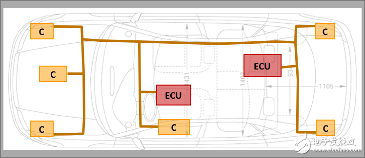
A platform architecture with standardized functional containers (resources) and connection paths (carriers).
A single node of the platform is standardized as a resource: an electronic control unit (ECU) or a line replaceable unit (LRU), an electrical assembly, an electrical or ground conductor. They can be coupled via electrical or bus systems (CAN, LIN, Flexray, Ethernet, ARINC 429, etc.) or via optical or radio wave connections. These communication paths are called carriers.
Bulkhead Lamp,Led Bulkhead Lamp,Round Bulkhead Light,Bulkhead Ceiling Light
Changxing Fanya Lighting Co.,Ltd , https://www.fyledlights.com