Differential pair: what you really need to know
The thirst for speed is always growing, and the transmission rate doubles every few years. This trend is common in many modern communication systems such as PCIe for computing, SAS and SATA storage, and Gigabit Ethernet in cloud computing. The information revolution poses a huge challenge to transmitting data over transmission media. Current transmission media still rely on copper wire, the signal rate in the data link can reach more than 25 Gbps, and the port throughput can be greater than 100 Gbps.
These serial data transmission designs use differential signaling to transmit data through a pair of copper wires called differential pairs. The signals in the A and B lines are equal amplitude, antiphase high speed pulses. Differential signals are used on many circuits, such as LVDS, CML, and PECL.
Transmitting an ideal serial bit stream
A serial bit stream is a differential signal that propagates through a differential pair. As shown in Figure 1, the estimated arrival times of the differential signals are the same, so that they maintain the properties of the differential signal (equal amplitude, anti-phase) at the receiving end. A receiver is used to recover the signal and then correctly sample and recover the data for error-free data transmission.
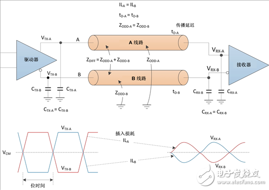
Figure 1: Electrical properties of an ideal differential pair
Requirements for differential pairs
A well-designed differential pair is a key factor in successful high-speed data transmission. Depending on the application, the differential pair can be a pair of printed circuit board (PCB) traces, a pair of twisted pairs or a pair of shared insulated and shielded parallel lines (commonly referred to as Twin-axial cables). In this series, I will discuss the characteristics of differential pairs and design issues and solutions for high-speed data transmission.
In the first part of this series, let's examine the main requirements for differential pairs:
Both A and B lines need to maintain a fairly constant and equal characteristic impedance, commonly referred to as odd-mode impedance, where both lines are differentially excited.
The differential signal should maintain the properties of the differential signal when it reaches the destination: almost equal amplitude and opposite phase.
The insertion loss of each line should be approximately equal.
The propagation delay for each line should be approximately equal.
In summary, we should seek an equal and fairly constant odd-mode impedance to minimize impedance fluctuations over the length of the differential pair from source to destination. We should also match the delay match and insertion loss between the A line and the B line. In addition, we need to ensure that the insertion loss is not too much, so that the receiver can recover the data correctly.
In order to meet the above requirements, the A and B lines should maintain high symmetry in their physical layout. The transmitter and receiver should also maintain high symmetry in their A and B line circuits such that their electrical loads on the A and B lines are equal.
Design differential pairs to minimize distortion
Ideally, the differential pair is completely symmetrical, with infinite bandwidth and complete isolation between adjacent signals. In the real world, differential signals are propagated through integrated circuit (IC) packages, external devices, different PCB structures, connectors, and cable connection subsystems. Achieving a perfectly symmetric differential pair is not easy. In a future blog post, I will discuss the scheme of differential pair design and the technique to minimize distortion of the transmitted signal.
Texas Instruments has a complete line of high-speed signal conditioning ICs, such as ReTImer and Redriver. They help to solve the undesirable conditions of all types of actual differential pair designs and high insertion loss conditions, enabling reliable data communication and extended transmission distances in modern systems.
Electronic Fireproof Safes
Safes that can resist fire for 0.5 hour.
Details:
Special fireproof material stuffing which resist damage;
Seamless molding case;
Heavy duty style doors and hinges;
Anti-drilling, anti-burglar and anti-force;
Yongfa patent: dual system protection;
Fire proof for 1 hour and it can ensure an inner temperature to be less than 177°C(350°F), while exposed to 927°C(1700°F) flames;
Strong hinges and door-bolts;
0.5 Hour Fireproof Safe,Mechanical Fireproof Safes,Electronic Fireproof Safe,Fireproof Ammo Safes,Fireproof Safes
YONGFA INTELLIGENT TECHNOLOGY SECURITY CO., LTD. , http://www.yongfa-safe.com