Design of Engine Calibration Diagnostic System Based on ASAP Standard
Abstract: A calibration and diagnosis system based on ASAP standard is designed by layering and modularization. The software uses the software watchdog technology in the host computer to solve the problem of rapid fault location between the calibration tool and the engine electronic control unit. When the fault occurs, the host computer automatically saves the calibration data, and automatically issues the calibration data after the fault is repaired, thereby preventing the calibration data from being lost and avoiding the repetitive calibration work. And can read the database file of the foreign calibration system, its reliability and versatility are further enhanced.
Keywords: calibration system; engine; diagnosis; ASAP standard; software watchdog
Design of engine calibration diagnosis system based on ASAP standards
Li Yin-guo Cao Geng-yan Cen Ming (Chongqing University of Posts and Telcoms, Chongqing China 400065)
Abstract:A calibration and diagnosis system based on ASAP standards was designed using layer and modularization idea. the malfunction between host computer and ECU was positioned quickly
Through the software watchdog technology in the host computer. and the calibrated datas were autosaved into the Caliration tool. After the malfunction was repaired ,these datas were sent to the RAM of ECU. So this can avoid the datas'losing and the calibration's repetition. Also it can read foreign calibration software's description file.it's reliability and universality was strengthened.
Key words:calibration system, Engine, diagnosis, ASAP standards , Software Watchdog
Introduction The engine electronic control unit (ECU) is the core of the vehicle engine control system. It can provide the best air-fuel ratio and ignition time according to the operating conditions of the engine, thus optimizing the engine's power, economy and exhaust emissions. [1]. It is therefore important to develop a calibration tool that is reliable, convenient and flexible. It can shorten the development cycle of the ECU.
Reduce the matching experiment workload, reduce development costs, and help the calibrator get the best calibration parameters in a short time.
From the existing data, the calibration system designed in China generally has calibration, monitoring and diagnostic functions. However, its diagnostic function is only displayed on the host computer for the fault information provided by the ECU. There is no introduction in the fault location and repair between the host computer and the ECU. In addition to online calibration, real-time monitoring and the ability to read the fault information in the ECU, the calibration diagnostic system designed in this paper uses the software to gate the calibration. The dog technology realizes the rapid positioning of the fault between the upper computer and the ECU, and has the functions of automatically saving, loading, and reading back the comparative data. Enhanced reliability and flexibility of the calibration system.
1 ASAP Standard Architecture
ASAP (Arbeitskreis zur Standardisierung von Applikationssystemen) refers to the application system standardization organization, which is proposed to make the tools and methods used in the development of automotive electronic products compatible and interchangeable [2]. In order to achieve measurement, calibration and diagnosis of the application system, the ASAP working group is based on MCD (Measurement,
The Calibration and Diagnostics model divides the standard into three sub-criteria, ASAP1, ASAP2, and ASAP3.
The ASAP1 standard provides an interface between the application system and the control device; the ASAP2 standard provides a standardized description of various internal parameters of the ECU, external interface information, and communication methods. The ASAP description file generated according to this standard is various types of control devices. Data exchange platform; ASAP3 standard provides a unified interface between the automatic system (or user) and the MCD system. The user only needs to call the interface function provided by the MCD system to complete the functions of measurement, calibration and diagnosis.
2 The overall design of the calibration system uses a PC as the host computer, and is connected to the engine ECU through a USB-CAN communication card to achieve calibration of the engine ECU.
Monitoring, diagnosis, etc. The communication and data exchange platform between the host computer and the ECU is realized by the CCP protocol in the ASAP standard and the ASAP description file (.A2L file) generated by the ASAP2 standard, respectively. The PC calibration software is designed with layering and modularity, including data layer, presentation layer and communication layer (Figure 1). The data layer includes an initialization subsystem and a data management subsystem, and the initialization subsystem mainly performs operations such as initialization of the CAN communication module and data. The data management subsystem mainly performs operations such as data storage, loading, playback, and A2L database management; the presentation layer includes a calibration monitoring subsystem and a diagnostic subsystem, and the layer mainly performs operations such as calibration, monitoring, and diagnosis of the engine ECU; The communication layer mainly completes the communication operation between the host computer and the ECU.
This article refers to the address: http://

Figure 1 The overall framework of the calibration diagnostic system The A2l database generated by the ASAP editor is the data exchange platform of the entire calibration system. Therefore, the A2L file is first imported at the beginning of the system operation, and then the interface library function provided by the CAN communication module is called to complete the CAN communication module. Initialize and other operations,
Multiple ECUs can be calibrated and monitored after the connection is established. Fault diagnosis (ECU fault information upload display and calibration system fault diagnosis) runs through the calibration and monitoring process (Figure 2).
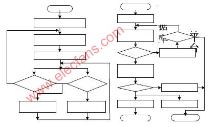
Figure 2 The main machine main flow chart Figure 3 Calibration data initialization flow chart
2.1 Initialization subsystem design In this subsystem, the initialization of the USB-CAN module, the initialization of the calibration parameters, and the initial configuration of the DAQ parameters are included.
The host computer performs the following initialization operations by calling the relevant interface library functions of the CAN communication module: opening the CAN communication module, selecting the CAN port connected to the ECU, and configuring the relevant parameters of each CAN port (acceptance code, mask code, timer, filter,
Mode, etc.), start CAN communication equipment, etc. There are two ways to initialize the calibration parameters: one is to read the calibration data from the RAM area of ​​the ECU to the upper computer calibration window, and the other is to load the calibration data from the calibration data file of the upper computer to initialize the calibration data (such as image 3). Before the monitoring parameters are uploaded, the DAQ configuration is performed on the data to be monitored, and the monitoring data of different uploading periods is configured into different DAQ tables, which requires the upper computer to send DAQ configuration commands and START_STOP command requirements.
The DAQ processor in the ECU configures and opens different DAQ tables for uploading and displaying monitoring data. During the calibration system operation,
By opening or closing a DAQ table, the data upload data of the opened DAQ table can be monitored in real time.
2.2 Data Management Subsystem Design In this subsystem, it mainly includes the functions of A2L database management, data saving, printing, playback and comparison.
The A2l database is the data exchange platform of the entire calibration system. It records detailed information such as various parameters, external interface information, and communication methods inside the controller. Therefore, its management is particularly important. The data is downloaded and modified by using the method of combining the length of the data segment in the communication protocol. The upper computer program is responsible for querying the A2L database to obtain information such as the address of the control parameters and the length of the data segment [3]. The use of the A2L database reduces the burden on the ECU to define and store a large number of calibration variables.
Reduce the computation time of the microprocessor. When the parameter information in the ECU changes, only the modified part of the original A2L file is refreshed with the ASAP database editor. The calibration system only needs to calibrate and monitor the ECU under the new A2L file. Therefore, when the ECU changes the information, it will not make any changes to the code of the calibration software, and also avoids the hidden troubles caused by the local modification of the internal code of the calibration software [4], which increases the flexibility of the calibration system.
In order to facilitate offline analysis and comparison of the monitored data, the system has the function of saving monitoring data and performing offline analysis, waveform playback and printing.
2.3 Design of the diagnostic subsystem In this subsystem, in addition to reading the fault information in the ECU, the calibration of the host computer uses the software watchdog technology to achieve rapid fault location of the calibration system, greatly reducing the fault finding time. The calibration data is saved in time when the fault occurs.
Avoid repetitive calibration due to loss of calibration data, and improve the reliability of the calibration system (Figure 4, Figure 5).
2.3.1 Fault rapid positioning and automatic data saving Set a global variable ConnectFlag in the receiving interrupt function of the host computer and assign its value to 0, as long as the monitoring data is periodically uploaded (the data uploading period of the three DAQ tables in this paper is 10ms, 20ms, 50ms) ConnectFlag has been
0, when it exceeds 50ms, the variable will be incremented by 1 in the timer function. When it is greater than the specified value (no data is uploaded within the specified time), a fault message appears on the host computer. According to the interface function provided by USB-CAN, it is judged that the fault is ECU.
Between the USB-CAN module and the USB-CAN and ECU. In the event of a fault, the upper computer calls the save function to save the calibrated data, and backs up the calibration data to avoid recalibration due to the loss of calibration data, reducing the calibration workload.
2.3.2 Fault repair and automatic loading of data According to the fault prompt, the fault location can be quickly determined. After the fault is removed, click the reset button in the repair menu of the main interface according to the fault prompt. The reset is successful and the calibration data is automatically saved from the saved file of the host computer. Loaded into the calibration window and delivered,
Then continue the calibration operation without recalibration. In the repair menu, when the ECU is powered off, when the ECU is repaired after power-on, the host computer needs to re-issue the DAQ command and start the DAQ table and other related commands, because once the power is turned off or reset,
The commands related to the ECU and the host computer need to be resent to complete the communication between the two; for the line fault between the ECU and the USB-CAN, simply connect the line to continue the communication between the host computer and the ECU; for USB -CAN and the host computer failure situation, you need to close the CAN-USB device in the host computer and then open and initialize the device, and then continue the calibration work.
2.4 Calibration monitoring subsystem design The online calibration of ECU control parameters is completed in the calibration window of the upper computer. By modifying the parameter values ​​in the calibration window online, the relevant parameter values ​​of the RAM area in the ECU can be optimized, and the calibration value of the RAM area is programmed into the FLASH after calibration. At the same time, the calibration parameter value in the ECU can be read as the standard stator window and compared with the current calibration window value to ensure the correctness of the calibration value. The calibration flow chart is shown in Figure 4. In addition, the subsystem can monitor the data collected by the ECU in real time and display the data in a variety of ways, which can visually display the monitored data and its changing rules. The host computer can send the DAQ monitoring data automatically from the device periodically by sending a command at a time (see Figure 5 for details).
2.5 Communication Subsystem Design The communication subsystem mainly provides a communication interface between the host computer and the ECU. The communication protocol used is the CCP protocol [5], which is a communication standard independent from the ASAP1a sub-standard. The protocol has the advantages of reliable communication, strong real-time performance and good versatility. In the design, through the ccpCommand () function call different CCP command to complete the command delivery, call fGetData ()
The function receives the return command of the ECU and reads the monitoring data uploaded in the ECU. The ECU DAQ PC configuration commands and start DAQ command to periodically upload the monitoring data.

Figure 4 Calibration flow chart Figure 5 Monitoring flow chart
3 Calibration system design of the underlying software

Figure 6 The underlying software design is shown in Figure 6. In order to increase the versatility of the underlying communication module, a modular design concept is adopted, which will be CAN Driver.
Separated from the CCP Driver. The Command processor is the main component of the CCP Driver; the DAQ processor is used to collect and periodically upload the current values ​​of the monitoring parameters of different DAQ tables as required. The two processors form the CCP Driver of the controller,
It is the analysis and implementation of the contents of the calibration protocol. In order to ensure the reliability of CAN communication, the CAN Driver adopts a ring buffer mechanism and communicates interrupt subroutines and system tasks through operating system messages. The transplantation of different ECU hardware platforms can be realized by changing the CAN Driver, and the new ECU can be calibrated, which increases the compatibility and versatility of the underlying communication module.
4 Conclusion The calibration diagnostic system designed in this paper integrates functions such as calibration, monitoring and diagnosis. On the basis of ensuring the flexibility of the system and the real-time communication, the PC uses the software watchdog technology to realize the rapid diagnosis and repair of the calibration system fault.
The automatic data saving and loading functions prevent the loss of calibration data, avoid repetitive calibration work, and ensure the reliability of the entire calibration system. Experiments show that the system has high real-time performance, flexibility and reliability.
Vacuum Robot is floor vacuum clean robot ,its smart and small robot cleaner,very convient and free use it. Robot vacuum with Intelligent planning path, memory family layout, cleaning every corner and WIFI connect mobile phone, Timing boot, Automatic Cleaning for Home and Office, Automatic charging.
Application:Vacuum Cleaning Robot use in home,hotel,office and other area.this robot vacuum clean floor,table,glass,dry and wet clean.
Vacuum robot with two facotry in china shenzhen and ningbo,welcome to visit facotry,we are 10years manufacture experience.


Vacuum Robot
Vacuum Robot,Home Vacuum Robot,Floor Vacuum Robot Cleaner,Vacuum Robot With Water Tank
Zhengzhou Bangmi Smart Technology Co., Ltd. , http://www.globalcleanrobot.com