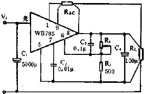
Current limiting protection application circuit diagram
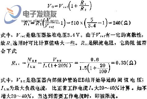
The figure shows the WB705 multi-terminal adjustable positive integrated voltage regulator to form an output voltage of 5V, output current 1.5A current-limiting protection application line, the maximum input voltage of this line is 16.8V, the minimum input voltage is 12.1V.C1 It is a filter capacitor, and the capacitance is selected according to the current capacity. The larger the load current is, the larger the capacitance is required to reduce the pulsation amount at the input end of the regulator; C2 is the compensation capacitor to prevent oscillation.
This article refers to the address: http://
SHENZHEN CHONDEKUAI TECHNOLOGY CO.LTD , https://www.szsiheyi.com